background image

Antaira Technologies - Industrial Ethernet Switches 
LNX-1600-E Series - Hardware Manual - v1.0 


1.2 Package Contents 

-

LNX-1600-E(-T) 

-

Quick Installation Guide 

-

Wall mounting bracket set with screws 

-

Dust cover set 

1.3 Safety Precaution 

Attention:​ If the DC voltage is supplied by an external circuit, please use a protection device on the power 

supply input. The industrial Ethernet switch’s hardware specs, ports, cabling information, and wiring 

installation will be described within this hardware manual. 

 
Attention:​ Si la tension CC est fournie par un circuit externe, veuillez utiliser un dispositif de protection sur 

l'entrée d'alimentation. Les spécifications matérielles, les ports, les informations de câblage et 

l'installation du câblage du commutateur Ethernet industriel seront décrits dans ce manuel d'utilisation. 

 
Warning Labels 

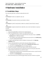
The caution label means that you should check certain information on the user manual when working 

with the device. (Shown in ​Figure 1.1​

 
Étiquettes d'avertissement 

L'étiquette d'avertissement signifie que vous devez vérifier certaines informations sur le manuel 

d'utilisation lorsque vous travaillez avec l'appareil. (Montré dans la ​figure 1.1​

Figure 1.1 - Caution Label 

Figure 1.1 - Étiquette de mise en garde 

Figure 1.2 - Hot Surface Warning Label 

Figure 1.2 - Étiquette d'avertissement de surface chaude 

Summary of Contents for LNX-1600-E Series

Page 1: ...LNX 1600 E Series 16 Port Industrial Unmanaged Ethernet Switch with 16 10 100Tx 12 48VDC Power Input E mark Version Hardware Manual Version 1 0 January 2021 ...

Page 2: ...d fitness for a particular purpose Antaira Technologies LLC may make improvements and or changes to the product and or specifications of the product described in this manual without prior notice Antaira Technologies LLC will not be liable for any technical inaccuracies or typographical errors found in this guide Changes are periodically made to the information contained herein and will be incorpor...

Page 3: ...ions radio si l équipement n est pas installé et utilisé conformément aux instructions Cependant il n y a aucune garantie qu aucune interférence ne se produira dans une installation particulière Si cet équipement provoque des interférences nuisibles à la réception radio ou télévision ce qui peut être déterminé en éteignant puis en rallumant l équipement l utilisateur est encouragé à essayer de cor...

Page 4: ... Industrial Grade Managed Ethernet Switches Hardware Manual Version 1 0 January 2021 The manual supports the following models LNX 1600 E LNX 1600 E T This document is the current official release hardware manual Please check our website www antaira com for any updated manual or contact us by e mail support antaira com ...

Page 5: ...3 2 1 Physical Dimensions 3 2 2 Front View Panel 4 2 3 Top View Panel 4 2 4 LED Indicators 5 2 5 Ethernet Ports 5 2 6 Cabling 6 2 7 Wiring the Power Inputs 6 2 8 Wiring the Fault Alarm Contact 7 2 9 Grounding Note 8 3 Mounting Installation 9 3 1 DIN Rail Mounting 9 3 2 Wall Mounting 10 4 Hardware Installation 12 4 1 Installation Steps 12 4 2 Maintenance and Service 13 4 3 Troubleshooting 13 5 Tech...

Page 6: ...8VDC There are two wide operating temperature models to support either a 10 C to 65 C or 40 C to 75 C environment There are also two wide operating temperature models for either a standard temperature range STD 10 C to 65 C or an extended temperature range EOT 40 C to 75 C 1 1 Product Hardware Features System Interface and Performance All RJ45 ports support Auto MDI MDI X Function Embedded 16 10 1...

Page 7: ...lez utiliser un dispositif de protection sur l entrée d alimentation Les spécifications matérielles les ports les informations de câblage et l installation du câblage du commutateur Ethernet industriel seront décrits dans ce manuel d utilisation Warning Labels The caution label means that you should check certain information on the user manual when working with the device Shown in Figure 1 1 Étiqu...

Page 8: ...ernet Switches LNX 1600 E Series Hardware Manual v1 0 2 Hardware Description 2 1 Physical Dimensions Figure 2 1 below shows the physical dimensions of this product series W x D x H is 46mm x 99mm x 142mm Figure 2 1 Physical Dimensions 3 ...

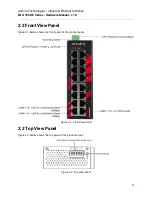
Page 9: ...NX 1600 E Series Hardware Manual v1 0 2 2 Front View Panel Figure 2 2 below shows the front panel of the product series Figure 2 2 Front View Panel 2 3 Top View Panel Figure 2 3 below shows the top panel of the product series Figure 2 3 Top View Panel 4 ...

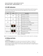
Page 10: ...ensing for 10 100Base T or 100Base TX connections Auto MDI MDI X means that the switch can connect to another switch or workstation without changing the straight through or crossover cabling See the figures below for straight through and crossover cabling schematics 5 LED Color Description P1 Green On Power Input 1 is active Off Power Input 1 is inactive P2 Green On Power Input 2 is active Off Pow...

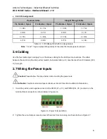
Page 11: ...th 2 7 Wiring the Power Inputs Caution Please follow the steps below when inserting the power wire Attention Veuillez suivre les étapes ci dessous lors de l insertion du câble d alimentation 1 Insert the positive and negative wires into the PWR1 V1 V1 and PWR2 V2 V2 contacts on the terminal block connector as shown below in Figure 2 6 Figure 2 6 Power Terminal Block 2 Tighten the wire clamp screws...

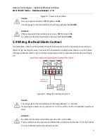
Page 12: ...ector as the picture shows below in Figure 2 8 By inserting the wires it will detect the fault status including power failure or port link failure managed industrial switch only and form a normal open circuit An example is shown below in Figure 2 8 Figure 2 8 Wiring the Fault Alarm Contact Caution The wire gauge for the terminal block should range between 12 24 AWG If only using one power source j...

Page 13: ...etic Interference EMI Run the ground connection from the ground screw to the grounding surface prior to connecting devices The grounding screw symbol is shown below in Figure 2 9 Figure 2 9 Grounding Screw Symbol Caution Using a shielded cable achieves better electromagnetic compatibility Attention L utilisation d un câble blindé permet une meilleure compatibilité électromagnétique 8 ...

Page 14: ...rear side of the industrial Ethernet switch Caution The torque for tightening the screws on the device is 3 5 in lbs Attention Le couple de serrage des vis sur l appareil est de 3 5 pouces livres 2 To remove the DIN Rail bracket do the opposite from step 1 3 After the DIN Rail bracket is installed on the rear side of the switch insert the top of the DIN Rail on to the track as shown below in Figur...

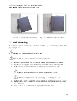
Page 15: ... industriel 1 Remove the DIN Rail bracket from the industrial Ethernet switch by loosening the screws 2 Place the wall mounting brackets on the top and bottom of the industrial Ethernet switch 3 Use the screws to screw the wall mounting bracket on the industrial Ethernet switch Caution The torque for tightening the screws on the device is 3 5 in lbs Attention Le couple de serrage des vis sur l app...

Page 16: ...trial Ethernet Switches LNX 1600 E Series Hardware Manual v1 0 Figure 3 4 Remove DIN Rail bracket from the Switch Below in Figure 3 5 are the dimensions of the wall mounting bracket Figure 3 5 Wall Mounting Bracket Dimensions 11 ...

Page 17: ...f it is required to wall mount the industrial Ethernet switch please refer to the Wall Mounting section for wall mounting installation 3 To hang the industrial Ethernet switch on a DIN Rail or wall please refer to the Mounting Installation section 4 Power on the industrial Ethernet switch and then the power LED light will turn on For the help on how to wire power please refer to the Wiring the Pow...

Page 18: ...is being used Never use a power supply or adapter with a non compliant DC output voltage or it will burn the equipment Select the proper UTP or STP cable in order to construct the network Use an unshielded twisted pair UTP or shield twisted pair STP cable for RJ45 connections 100Ω Category 5e for 10 100Mbps Also be sure that the length of any twisted pair connection does not exceed 100 meters 328 ...

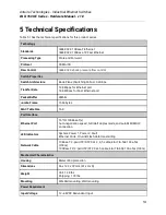
Page 19: ...port 148 800pps for Fast Ethernet port Packet Buffer 4Mbits Jumbo Frame 1664 bytes MAC Table Size 16K Port Interface Ethernet Port 16 10 100Base T x Auto negotiation speed Full Half duplex mode and auto MDI MDI X connection LED Indicators System Power 1 Power 2 Fault Ethernet Ports On Link Flash data transmitting Network Cable 10Base T 2 pair UTP STP Cat 3 4 5 cable EIA TIA 568 100 ohm 100m 100Bas...

Page 20: ...nced on the Antaira website 15 Power Connection 1 removable 6 contact terminal block Relay Contact 24VDC 1A resistive Overload Current Protection Present Reverse Polarity Protection Present System Power Consumption 3 4 Watts Environmental Limits Operating Temperature STD 10 C to 65 C EOT 40 C to 75 C Storage Temperature 40 C 85 C Ambient Relative Humidity 5 to 95 non condensing Regulatory Approval...

Reviews: