GT3000
STO Function
IMGT30017EN
69
In order to meet the safety requirements of UNI EN 954-
1:1998, category 3, an external safety circuit is required that
shall meet:
the redundancy principle in respect of the activation
inputs of the two channels, so that a single failure in any
of these parts does not result in the loss of the safety
function, having regard to common failures; for this
reason, two separate independent inputs are provided;
the monitoring of the correct activation of both channels;
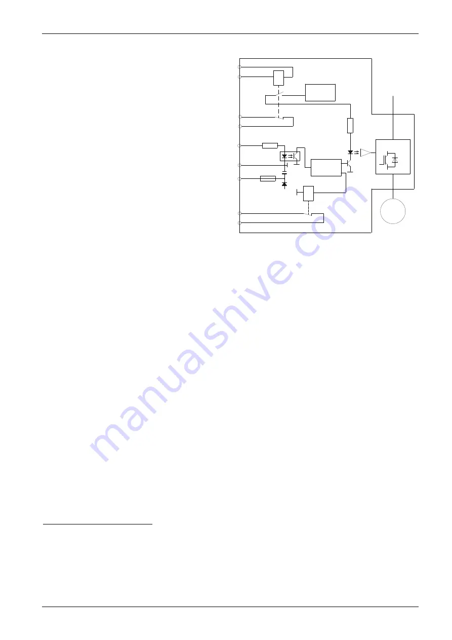
two contracts have been provided outside terminals
XM70-3 – XM70-4 and XM1-2 - XM1-43, relating to two
independent relays: RL1 (safety relay) and RL2. Both of
them are “open” under normal operating conditions and
“closed” when the STO function is activated: an external
parity check is thus possible, which includes a comparison
between the two outputs. If a failure is identified, it must be
possible to reset the circuit.
For further information about the actions to be taken when a
failure is identified and the intervention times see paragraph
6A.6.2.2.
STO function for GT3000 – Block diagram
6A.6.2.2 Safety configurations with converters featuring the "STO" function
Note
: we are not going to analyse the types and configurations typical of standard converters, without the "STO" function (that shall include
both the use of external remote control switches provided with “mirror” contacts, to check their actual operation, and the management
of the drive enable).
The "STO" safety function can be adopted in two different configurations, using a PLC or safety control units, according to the requested
safety category:
1.
use of the standard version (channel 1 and channel 2), to meet the safety requirements of UNI EN 954-1:1998, category 3;
2.
use of the safety relay only (channel 1), to meet the safety requirements of UNI EN 954-1:1998, category 2;
When the "STO" safety function is used according to category 3:
-
make sure that a single failure of the safety components does not determine the loss of the safety function; for this reason the
circuit entering the two channels must be performed according to this requirement and
-
plan some tests to identify, if possible, any single failure during or before the subsequent request for the safety function.
In both configurations, contacts are provided without output potential, in order to verify the correct activation of the STO function.
When the "STO" safety function is used in category 2, verify the safety function when power is supplied and before any hazardous situation
and/or from time to time during operation. In this case, you can use the contact outside terminals XM70-3 – XM70-4.
Warning!!
Only qualified personnel shall configure the STO function.
6A.6.2.2a
Configuration according to category 3 EN 954-1:
The following items are required upon every single request for the safety function:
Opening control of DRIVE ENABLE (XM1-20);
Relay RL2 signals the pulse block by closing the auxiliary contact on terminals XM1-2, XM1-43;
Switch off P24EX, supply to the "STO", terminal XM70-1;
The "STO" will close the contact on terminals XM70-3 – XM70-4, and this indicates that pulse supply has been cut-out;
Reasonableness check (between input control and output feedback) and/or discrepancy check (simultaneous switching of both signals) of the
two signals available, respectively, on terminals XM70-3 – XM70-4 and on terminals XM1-2, XM1-43, and automatic activation of the "STO"
alarm procedure in case of faulty switching of both signals. This alarm procedure shall include the inhibition of both channels of the DRIVE
ENABLE (XM1-20) and of the "STO" of terminal XM70-1, and the operating sequence cannot be reset until the failure is removed
Warning!!
The adopted monitoring technique shall identify the failures in conductors of feedback signals, or they shall be protected from short-
circuits.
1
Note about the applications with interlocked guard provided with block:
In some applications an interlocked guard provided with block protects the access to the hazardous area. In this case, in both configurations, motion in the hazardous
area protected by the guard shall be controlled only if the guard is closed and locked and its unlocking is subject to the actual enabling of the STO function.
A)
Unlocking subject to enabled STO
In this case the guard unlocking condition is subject to:
the motor, which shall be stopped, by a signal from the drive and the enabling of the STO function, by NC feedback contacts.
B)
Unlocking NOT subject to STO
In this case the only unlocking condition is the “motor stopped” signal. The unlocking of the guard does not affect the inputs of the STO function, which is enabled when
the guard is opened.
Channel 1 Feedback
Channel 2 Command
Channel 2 Feedback
Channel 1 Command
XM1-2
XM1-20
XM1-43
XM1-24
XM1-25
XM70-4
XM70-3
XM70-2
XM70-1
M
Power
Module
Input Power
Gate Drive
Control Circuit
Gate Drive
Power Supply
+24V
RL2
RL1
Summary of Contents for GT3000
Page 1: ...GT3000 Hardware Software Manual www answerdrives com ...
Page 2: ......
Page 4: ......
Page 8: ...Table Of Contents GT3000 iv IMGT30017EN ...
Page 12: ...General Safety Precautions viii IMGT30017EN ...
Page 25: ...GT3000 Technical Data IMGT30017EN 13 Frames IV V VIN SVGT045 166 IP20 ...
Page 26: ...Technical Data GT3000 14 IMGT30017EN Frames IV V VIN SVGT045 166 IP54 ...
Page 28: ...Technical Data GT3000 16 IMGT30017EN Frames VII VIII IP00 SVGT200 521K SVGT200 470F ...
Page 29: ...GT3000 Technical Data IMGT30017EN 17 F series Frames 2xVII 2xVIII Parallel IP00 SVGT520 940M ...
Page 30: ...Technical Data GT3000 18 IMGT30017EN K series Frames 2xVII 2xVIII Parallel IP00 SVGT580 960K ...
Page 36: ...Installation GT3000 24 IMGT30017EN 3A 2 1 4 Frames VII VIII Installatiion ...
Page 58: ...GT3000 Installation 46 IMGT30004EN ...
Page 107: ...GT3000 Terminal Boards and Power Schematics IMGT30017EN 95 ...
Page 110: ...Terminal Boards and Power Schematics GT3000 98 IMGT30017EN ...


