


9
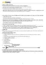
To adjust the torque on these screwdrivers. Proceed as follows :
1.
Determine the torque output of the tool by checking a tightened Fastener with a torque wrench.
2.
Increase or decrease the torque by rotating the Spring Adjusting Ring. Rotating the Ring clockwise to a higher number on the
torque Scale increase torque output while rotating the Ring counterclockwise to a lower number decreases the torque output.
3.
Check the adjustment with a torque wrench. A number of factors will affect torque output from one job to another. Final torque
adjustment should be made at the job through a of series of gradual increase. Always start below the desired torque and work
upward.
4.
Adjust the bit torque by changing the driving in length of the adjust ring at the end.
5.
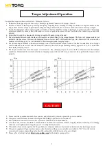
The relationship between torque scale and bit torque is as shown Ring, in the torque diagram. The figures of torque scale do not
indicate bit torque values. However, the clamping torque of screw itself is different form type, size, material of the screw and the
material of its mating part. Use it as standard to obtain an appropriate clamping torque.
6.
The (Return torque method) in which once-clamped screw is returned with torque wrench or the like is available as one of torque
control methods however, note that the measured values by the return torque method generally appear in 10%~30% lower than
the actually clamping torque.
7.
The torque checker measures the torque of screwdriver. The clamping torque of screw itself is different from the clamped
conditions. Understand the correlation between clamping torque values and the torque checker values perform the torque control
properly.
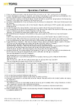
1.
Please read the operation manual before you use, and follow safety rules to operate the power controller.
2.
The power controller must be used with original MYTORQ 6-pin Electric Screwdrivers.
3.
MY5-TR0309
Series electric screwdriver collocates with MYP32-300N additional.
4.
Also in reverse rotation, the clutch is turned off in such manner as in normal rotation, stopping the motor running. Accordingly,
when the screw tightened at a large torque, set it to a higher torque scale.
5.
The number from zero to eight on the Torque Scale are reference number only and not an indication of actual torque output .
6.
The power supplier will generate low power when the button of the power controller is switched to "LO." Also, the electric
screwdriver's torque output setting value should be adjusted to middle torsion value accordingly.
7.
Please refer to Anlidar website
for the detail component list.
CAUTION
Torque Adjustment Operation


