


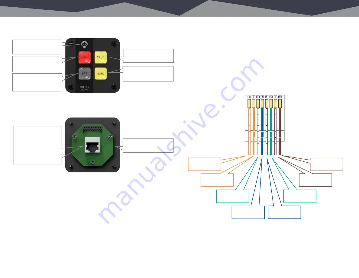
Buttons on the front.
Plugs on the back.
Connections.
The Button Gizmo is designed to behave as a plug-and-play Guest Mic Control
Panel for Axia consoles. You will need one available GPIO port for each Button
Gizmo. Simply plug the included RJ45F to DB15M adapter into the back of the
Button Gizmo, then connect it to the GPIO port with a standard CAT5 Ethernet
cable. For the curious, a breakout of the wiring is provided on Page 7.
Other manufacturers use different pin-outs and logic signals, so please consult
your console manual for details and refer to the RJ45 pinout on Page 6. We’ve
thoughtfully included an RJ45F to screw terminal breakout adapter to make
things easier.
RJ45 Pinout.
Pin 1 Button 1 Closure to common while Button 1 is pressed
Pin 2 Button 2 Closure to common while Button 2 is pressed
Pin 3 Button 3 Closure to common while Button 3 is pressed
Pin 4 Button 4 Closure to common while Button 4 is pressed
Pin 5 Lamp 1 Illuminates Button 1 LED when connected to common
Pin 6 Lamp 2 Illuminates Button 2 LED when connected to common
Pin 7 Common Connect to logic common on your GPIO port
Pin 8 V+
Connect to +5VDC or +12VDC on your GPIO port
5 Buttons and Connections
RJ45 Pinout 6
5 Buttons and Connections
RJ45 Pinout 6
Plugs on the back.
RJ45F connector. Use the
RJ45F to screw terminal
adapter to connect to any
console with GPIO logic,
or the RJ45F to DM15M
adapter for Axia consoles.
Both are included.
Buttons on the front.
Button 3 – Illuminates
yellow while button is
pressed.
Button 2 – Illuminates
yellow during external
closure to common.
Button 1 – Illuminates red
during external closure to
common.
RJ45 Pinout.
Pin 1 Button 1 Closure to common while Button 1 is pressed
Pin 2 Button 2 Closure to common while Button 2 is pressed
Pin 3 Button 3 Closure to common while Button 3 is pressed
Pin 4 Button 4 Closure to common while Button 4 is pressed
Pin 5 Lamp 1 Illuminates Button 1 LED when connected to common
Pin 6 Lamp 2 Illuminates Button 2 LED when connected to common
Pin 7 Common Connect to logic common on your GPIO port
Pin 8 V+ Connect to +5VDC or +12VDC on your GPIO port
Angry Audio guy.
Everything pushes his
buttons.
Button 4 – Illuminates
yellow while button is
pressed.
Connections.
The Button Gizmo is designed to behave as a plug-and-play Guest Mic Control
Panel for Axia consoles. You will need one available GPIO port for each Button
Gizmo. Simply plug the included RJ45F to DB15M adapter into the back of the
Button Gizmo, then connect it to the GPIO port with a standard CAT5 Ethernet
cable. For the curious, a breakout of the wiring is provided on Page 7.
Other manufacturers use different pin-outs and logic signals, so please consult
your console manual for details and refer to the RJ45 pinout on Page 6. We’ve
thoughtfully included an RJ45F to screw terminal breakout adapter to make things
easier.
1 White/Orange
Button 1
2 Orange/White
Button 2
3 White/Green
Button 3
4 Blue/White
Button 4
5 White/Blue
Lamp 1
6 Green/White
Lamp 2
7 White/Brown
Common
8 Brown/White
V+
Installs easily into a 2 1/8”
round hole.