1 3
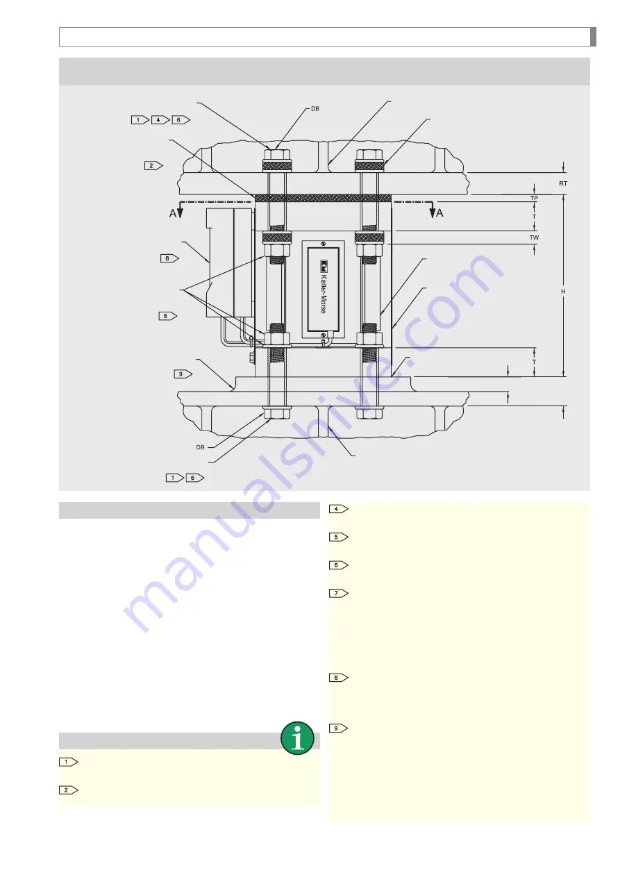
Figure 3
Beam Mounting
Notes
Bolts: ASTM A-325, bolt length determined by and
supplied by customer.
Pads: Supplied by Anderson-Negele
Operation and Installation
The Load Stand
®
II can compensate for thermally induced
expansion by slightly tilting the screws in oversized holes.
The mounting holes on the vessel should be of the same size
as the Load Stand
®
II („DH“) and their position should not be
more than ±1.5 mm (0.6") from their ideal position.
Level and fill with grout so that there is there is no gap
between the Load Stand
®
unit and the foundation. This is
mandatory to assure proper operation.
Customer provided loads and thermal expansion must be
must be taken into account so that applicable building codes
and and usage characteristics are met.
Load Stand
®
II has been designed in accordance with the
Uniform Builidng Code UBC, 1988 edition. Additional
information and test results can be obtained from Anderson-
Negele upon request.
Install upper mounting bolts in oversized holes (DH) and
tighten nuts 1/2 to 1 turns past “finger tight”.
XX = Maximum thermal deformation allowed, computed
as shown here : X = DH - DB - 1.5 mm (1/16”).
Use one of the following to prevent loosening Apply
double nut, adhesive or spoil bolt threads.
The loads listed are the maximum ASD loads for the
condition listed (Compression, Tension or Shear) and are
based on AISC 14th edition. All Load Stands must
be selected to resist the combined loading effects for
the specific jobsite and building code requirements.
Load combinations can be found in the applicable
building code.
Conduit entry sized for 3/4” NPT fitting. Use sealing
washers and flexible conduit (liquid tight recommend
-
ed) to maintain NEMA-4 rating and to de-couple conduit
run from the weighing system.
We recommend to insure system performance and
maximum loading capacity a rigid, flat mounting sur
-
face approximately twice dimension “A” long, the same
width as the flange , and a minimum of one half dimen
-
sion “T” thick. If the existing beam flange does not meet
these requirements plate can be welded to the beam
a shown, however the plate should be a minimum one
half dimension “T” thick.
Installation of the Load Stand
®
II
4 x ASTM A-325 Upper
mounting bolts (customer)
Vessel support
bracket (customer)
8 x Washer sets
(Anderson-Negele)
Rubber pad and washer
(Anderson-Negele),
shim as required
Junction Box Plastic or
Stainless Steel (Anderson-Negele)
4 x Microcell Strain gauge sensor,
part of Load Stand II
Sun shield, installed by the customer,
mounts under the Junction Box and to
the bottom flange of the Load Stand.
Sun shield and sun shield mounting
hardware supplied with each Load Stand
8 x Hardened washers
4 x Nuts
(customer)
Mounting plate (customer provided),
welded to the vessel support
beam all around if required
Shim
Min. T/2 (if applicable)
≥ T
Vessel support
beam (customer)
4 x lower mounting bolts
(customer)
Summary of Contents for Load Stand II
Page 23: ...23 Notes ...
Page 24: ...2 4 Notes ...


