background image


4

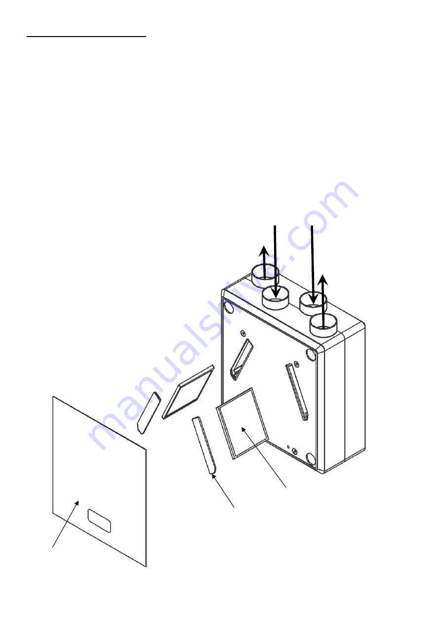
From atmosphere 

To atmosphere 

Extract from dwelling

Supply to dwelling 

2. PRODUCT  DESCRIPTION 


The DC Heat Recovery MVHR unit is a mechanical ventilation/heat recovery (MVHR) unit for domestic and 
commercial applications. It is designed for connection to 125mm-diameter ducting. 
The unit’s two fans and heat exchanger arrangement simultaneously supply and extract air while transferring heat 
from the stale exhaust airflow to the fresh intake airflow. This provides up to 91% heat recovery from the stale 
extracted air.  
Separation of the exhaust airflow and intake airflow is maintained throughout the unit. 
The fan motors have maintenance free, self lubricating long life bearings and are fitted with thermal overload 
protection, which in the event of a fault causing a motor to overheat will cut off the electrical supply to that motor. If this 
occurs, isolate the unit, check for any obstructions, leave the unit for a short time for the motor to cool before 
reconnecting the power supply. If the fault reoccurs, isolate the power supply and call a service engineer. 
The fans in this unit are low energy EC motors with a constant (100% adjustable) air volume. 
 
 
The EU3 filters in the unit ensure that the fresh supply air is clean as it enters the home. Also the extract air from the 
property is filtered to protect the heat exchanger from unwanted contamination.  Check filters regularly and clean if 
necessary.   
The unit is delivered complete with a mounting plate, fitting instructions, fixing kit and a condensation discharge fitting.  
 

Left Hand configuration shown 


Condensate exit on  
Atmosphere side 
(See connecting the 
condensate drain section). 

Front Panel 

Filter access covers 

Filters 

Summary of Contents for 443423

Page 1: ...Unit MVHR Wholehouse heat recovery unit Installation Maintenance Users Instructions PLEASE READ INSTRUCTIONS IN CONJUNCTION WITH ILLUSTRATIONS PLEASE SAVE THESE INSTRUCTIONS Stock Ref N DC Heat Recovery Unit MVHR 443423 ...

Page 2: ... 5 5 INSTALLATION DIAGRAM 6 6 CONNECTING THE CONDENSATE DRAIN 7 8 7 INSTALLATION 9 7 1 MOUNTING THE UNIT 9 7 2 CONNECTING THE DUCTWORK 9 8 ELECTRICAL CONNECTIONS 10 8 1 WIRING DIAGRAM 10 9 USER MAINTENANCE 11 9 1 CLEANING THE FILTERS 11 9 2 CLEANING THE HEAT EXCHANGER 12 10 SPARES 13 INSTALLATION CHECKLIST 14 ...

Page 3: ...0 DEGREES C 9 UNIT MUST BE SITED IN A FROST FREE LOCATION 10 SITE THE APPLIANCE AND ARRANGE THE ASSOCIATED DUCTING AND GRILLES TO PROVIDE A BALANCED CIRCULATION OF AIR 11 THE EXTERNAL INTAKE TERMINALS ASSOCIATED WITH THIS APPLIANCE MUST BE SITED AT LEAST 600mm AWAY FROM THE FLUE OF A FUEL BURNING APPLIANCE OTHER EXTERNAL GRILLE 12 ALL SAFETY REGULATIONS AND REQUIREMENTS MUST BE STRICTLY FOLLOWED T...

Page 4: ...the event of a fault causing a motor to overheat will cut off the electrical supply to that motor If this occurs isolate the unit check for any obstructions leave the unit for a short time for the motor to cool before reconnecting the power supply If the fault reoccurs isolate the power supply and call a service engineer The fans in this unit are low energy EC motors with a constant 100 adjustable...

Page 5: ...ws and plugs supplied vertically or horizontally Use the drilling template on the side of the box to locate the hole positions ensuring that there is enough space around the unit so that the duct work and the condensation drain can be fitted see pages 7 8 for details of which side of the unit the condensate drain should be fitted 3 Reassemble the DC MVHR unit in accordance with the diagram and tex...

Page 6: ...rotruding studs and keep in a safe place 5 Stand unit upright to separate the metal wall mounting plate from the bottom half of the casing Pull the casing forward leaving the rear protruding studs attached to the metal backplate 6 Secure the metal base plate with the rear studs still attached to the wall 7 Re assembly of the unit to the wall mounted backplate with the protruding studs is the rever...

Page 7: ...to be see page 8 for left and right hand positioning if mounting the unit vertically the condensate hole needs to be in position shown at its lowest point to allow the condensate to run out 3 image shown for right hand installation 3 If mounting the unit horizontally then position the condensate hole in position shown 4 image shown for right hand installation 4 Use a 20mm hole saw to cut out the c...

Page 8: ...HOME OUTSIDE LEFT HAND RIGHT HAND IMPORTANT FOR HORIZONTAL MOUNTING ENSURE 4 SLOPE DOWNWARDS TOWARDS CONDENSATE DRAIN POSITION TO ATMOSPHERE EXTRACT FROM DWELLING SUPPLY TO DWELLING SUPPLY TO DWELLING EXTRACT FROM DWELLING FROM ATMOSHERE TO ATMOSPHERE TO ATMOSPHERE FROM ATMOSHERE EXTRACT FROM DWELLING SUPPLY TO DWELLING SUPPLY TO DWELLING EXTRACT FROM DWELLING FROM ATMOSHERE TO ATMOSPHERE ...

Page 9: ...n is maintained to ensure proper drainage of condensation 7 2 Connecting ducts When the DC MVHR heat recovery unit has been installed the ducts can be fitted The ducts to and from the home are on one side of the unit The ducts to and from outside are on the opposite side In order to prevent condensation on the outside of the exterior air intake duct and the air exhaust duct both ducts must be insu...

Page 10: ...ion the fan should be started in High speed mode to ensure optimum performance of the fans and switched to the required continuous ventilation setting The fan speed controller must not be mounted above or closer then 1m to a cooker where it could be affected by excessive heat or moisture 8 1 Wiring Diagram A five speed control switch 3 x manual 2 x external sensors is supplied Each fan speed must ...

Page 11: ... pollution levels The filters should be replaced annually or after a maximum of 3 cleaning cycles 9 1 Cleaning the filters by user Switch off the power supply Remove front panel Carefully remove filter covers Carefully remove the 2 filters Gently vacuum the outside of the filters as shown After cleaning replace the filters Replace filter covers Replace front panel Switch power back on and check un...

Page 12: ...4 screws on the front of the unit Carefully remove the front half of the unit and put to one side 3 Carefully remove the heat exchanger Clean the heat exchanger with warm soapy water use a suitable sterilising agent to sterilise Allow to dry fully before proceeding 4 Reassemble the unit taking care not to damage the rubber seals ...

Page 13: ... Spares ITEM PART NUMBER DESCRIPTION 1 444364 FRONT COVER WHITE 2 444363 FILTER COVER SET OF 2 3 443889 FILTERS PACK OF 2 4 444362 HEAT RECOVERY CELL 5 444374 E C FANS 6 444360 CONDENSATION DRAIN 1 2 3 4 5 6 ...

Page 14: ...ntal with room around it to allow maintenance 2 Is any flexible ducting pulled taut to prevent moisture collection and avoids airflow issues 3 Is any flexible ducting crushed which will cause airflow issues 4 Are all joints in the ductwork sealed to prevent air leakage 5 Is the ducting insulated to prevent condensation and cooling or heating of the air 6 Does the condensate drain a have the correc...

Reviews: