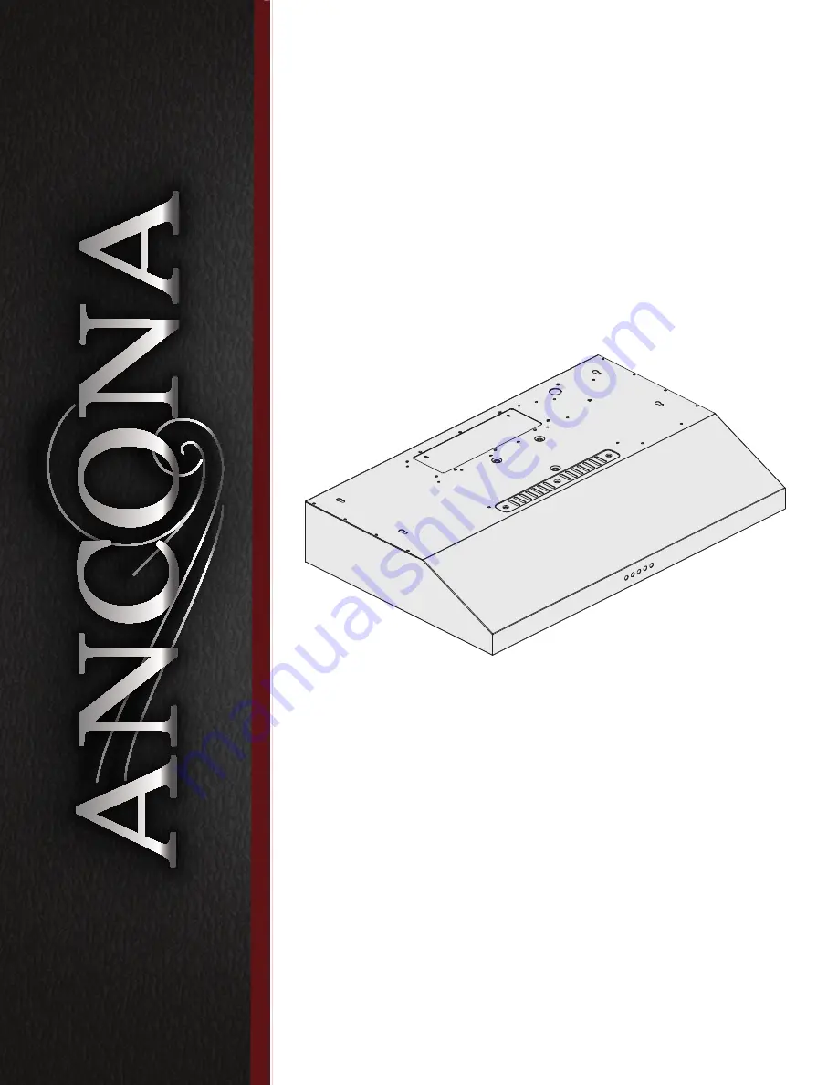
Ancona Slim S3D User'S Manual & Installation Instructions Download Page 1

®

Range Hood

Slim S3D and S3DW

30 inch

User Manual

&

Installation Instructions

IMPORTANT SAFETY INSTRUCTIONS

Carefully read the important information 

regarding installation, safety and maintenance. 

Keep these instructions for future reference. 

MAAN1292R-03

2019-03-04

Summary of Contents for Slim S3D

Page 1: ...0 inch User Manual Installation Instructions IMPORTANT SAFETY INSTRUCTIONS Carefully read the important information regarding installation safety and maintenance Keep these instructions for future ref...

Page 2: ...ERS Start Here Safety Instructions are on pages 4 and 5 and Operating Instructions are on pages 15 16 and 19 Please perform these steps 1 Read the safety instructions 2 Read all instructions in the ma...

Page 3: ...Step 5 Venting Installation Guidelines 9 Step 6 Create Exterior Ventilation New Installation Only 11 Step 7 Preparations 11 Step 8 Attaching Vent Damper 12 Step 9 Installing the Hood 12 Step 10 Electr...

Page 4: ...e service disconnecting means to prevent power from being switched on accidentally When the service disconnecting means cannot be locked securely fasten a prominent warning device such as a tag to the...

Page 5: ...ATE AND CALL THE FIRE DEPARTMENT b NEVER PICK UP A FLAMING PAN You may be burned c DO NOT USE WATER including wet dishcloths or towels a violent steam explosion will result d Use an extinguisher ONLY...

Page 6: ...rs will not be included due to the variation of cabinetry constructions and wall material Please consult your installation specialist regarding the optimal type of mounting screws and wall anchors to...

Page 7: ...Radio Frequency Interference Protected Motors Single Motor Control Mechanical control panel Filtration Charcoal filter Illumination 2 2 55 W LED Venting Size Top or rear 10 in 3 1 4 in 25 4 cm 8 3 cm...

Page 8: ...ill be installed A straight or short duct run will allow the unit to perform most efficiently Long duct runs elbows and transitions will reduce the performance of the unit Each elbow is equivalent to...

Page 9: ...of hood and duct cover For the most efficient and quiet operation It is recommended that the range hood be vented vertically through the roof through 6 in 15 3 cm or bigger round metal aluminum vent...

Page 10: ...ch 61 cm for electric cook tops and minimum of 30 inch 76 2 cm for gas stove tops and no higher than 30 inch 76 2 cm for electric cook tops It is important to install the hood at the proper mounting h...

Page 11: ...s necessary to install the hood turn OFF the power on an electric range at the main electrical box SHUT OFF THE GAS BEFORE MOVING A GAS RANGE Remove the two filters to allow access to the inside of th...

Page 12: ...ided on Page 7 measure and drill 4 holes into bottom of cabinet See Fig 7 If venting internally use measurements provided on Page 7 and clearance on Fig 1 If venting externally depending on exterior v...

Page 13: ...f an electrical short circuit grounding reduces the risk of electric shock by providing an escape wire for the electric current WARNING Improper grounding can result in a risk of electric shock Consul...

Page 14: ...nstall filters follow these four steps See Figure 10 Angle the filter into slots at the back of the hood Push the button on handle of the filter Release the handle once the filter fits into a resting...

Page 15: ...o operate at Low speed vPress the button and the motor will reach Medium speed wPress the button the motor will reach High speed xPress the button to turn the fan off Lights u Press the light button t...

Page 16: ...ly with insufficient duct size For example 7 in 17 7 cm duct over 6 in 15 2 cm hole and loosely secured Check if duct is clogged or if damper unit half circular flange is not installed correctly or op...

Page 17: ...ety screen 5 Cage plate 6 Propeller 7 Motor 8 Capacitor 9 Box cover 10 Housing 11 Lamp guide line 12 Propeller cage 13 Driver guide line 14 Strengthen strip 15 LED lamp driver 16 Housing cover 17 Wire...

Page 18: ...18 Assembly Circuit Diagram Blower assembly Electrical Assembly Number Part 1 Propeller Cage 2 Motor 3 Propeller 4 Cage Plate 5 Safety screen Number Part 1 Capacitor 2 Electrical box cover...

Page 19: ...rly Regular care will help preserve the appearance of the range hood Cleaning Exterior Surfaces Clean periodically with hot soapy water and clean cotton cloth DO NOT use corrosive or abrasive detergen...

Page 20: ...com Website www anconahome com Ancona is in association with Mr Appliance for all after sales service calls Please contact their service provider or visit their website Phone 1 888 998 2011 Website w...

Reviews: