

1.
Insert the CD provided in the Anaren
BoosterPack
kit,
and if prompted, click the “AIR BoosterPack Installation”
icon. If the CD menu does not automatically appear, click
“autorun.exe” in the CD root menu. Then click the
“MSP430” menu option.
2.
If using on a computer where the
LaunchPad
drivers
have not been previously installed, click the “Install
LaunchPad
USB Driver” menu option. The drivers are
automatically installed.
3.
Once the drivers are installed, follow the instructions in
the
LaunchPad
kit to verify hardware operation by running
the temperature measurement application.
Installation & Launch
:
(continued)
Still not connected? See User’s Manual for troubleshooting!
Installation & Launch (MSP430)
:
Follow these steps to launch the startup
application.
Note:
Instructions below are for the
MSP430 Value Line
LaunchPad.
If using the Stellaris
®
LaunchPad, see supplied instructions.
4.
Disconnect the
LaunchPad
from the computer, and if
required, solder the two 10-pin
male
headers to each
LaunchPad
.
5.
The MCUs required for operation come pre-mounted
on the
BoosterPacks
. Remove any MCUs mounted in the
LaunchPad
DIP sockets. A pocket for MCU storage is
provided in the
BoosterPack
plastic packaging.
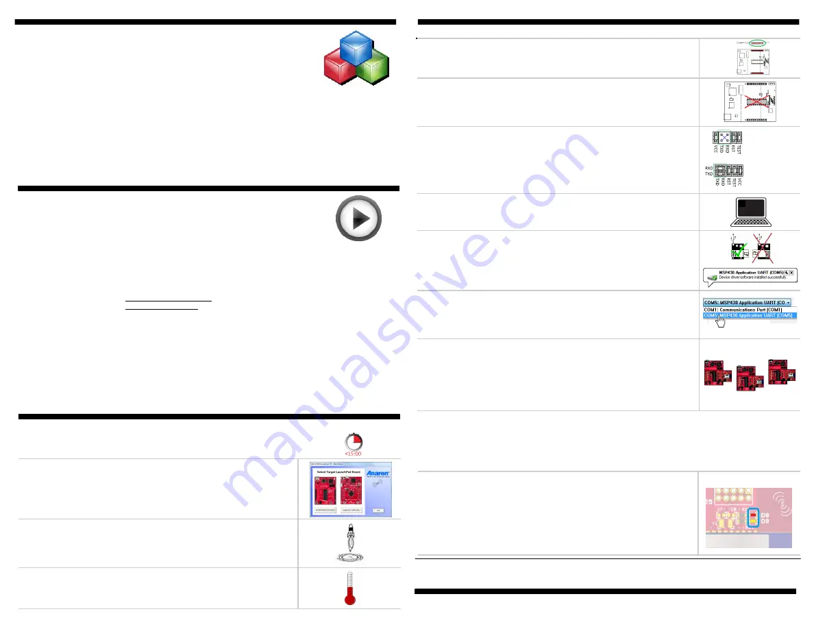
6.
For proper operation of the UART interface to the
computer, the
LaunchPad
J3 jumpers must be modified:
- For
LaunchPad
v1.4 and earlier, remove the TxD & RxD shunt
jumpers, and replace with an x-jumper (not included)
- For
LaunchPad
later versions, rotate the TxD and RxD shunt
jumpers 90 degrees, as shown to the right
v1.4 & earlier
Later versions:
7.
If a terminal emulation program is not already installed
on the computer, open the CD Additional Resources menu,
and select the “Go To Tera Term Home Page” option.
8.
Plug a
BoosterPack
into each
LaunchPad
, ensuring
proper orientation. Then connect the
Coordinator
BoosterPack
-
LaunchPad
combo to a computer,
using the
LaunchPad
kit USB cable. A message is
displayed confirming successful driver installation.
9.
Launch the terminal emulation program and select the
“MSP430 application UART” port created in step 7 from the
list of available ports. Press the
LaunchPad
reset switch to
display the initialization message in the window.
10.
Connect the
Router
BoosterPack
-
LaunchPad
combo
to a computer by USB cable. Data packets start displaying
in the Coordinator terminal window; example data packets
shown below. Repeat this step for the
End Point
. Separate
terminal windows may be opened to locally display Router
and End Point data by following step 9.
NEXT STEPS:
Now that the
BoosterPack
network is operating, start exploring the
many other development options. See User’s Manual and CD for more information.
Some building block examples:
Network:
(Get module version, Get MAC address, Read radio GPIO, RF tester, Range
test, Packet error rate test)
Sensors & Indicators:
(Read button push, Blink LED, Read light sensor, Read IR temp
sensor)
Other Functions:
(Send text to USB port, Read/write non-volatile memory)
Router (temperature):
From:00124B0001FE4710, LQI=BA, 2 KVPs received:
OID_VCC_MV(0x02) = 3535 (3.535V)
OID_TEMPERATURE_REMOTE(0x12) = 2306 (23.06C)
End Point (color):
From:00124B0001FE47CB, LQI=93, 5 KVPs received:
OID_VCC_MV(0x02) = 3505 (3.505V)
OID_COLOR_SENSOR_RED(0x22) = 127
OID_COLOR_SENSOR_BLUE(0x23) = 8278
OID_COLOR_SENSOR_GREEN(0x24) = 316
OID_COLOR_SENSOR_CLEAR(0x25) = 4401
Coordinator (C):
- Sends text data packets received from the Router and/or End Point module(s)
to a terminal emulation program
- Shows Router or End Point sensor status on RGB LED
Router temperature sensor: Shows color ranging from blue=’cold’ to red=’hot’
End Point color sensor: Shows color representing light incident on the sensor
- Blinks LED D1 when communicating with the Router or End Point
Router (R):
- Sends IR temperature sensor data over the RF network to the Coordinator,
and to local USB port for display on a terminal emulation program
- Displays link status on the green segment of the RGB LED
- Displays communication with the Coordinator or End Point by blinking the
blue segment of the RGB LED
End Point (E):
- Sends RGB color sensor data over the RF network to the Coordinator, and to
local USB port for display on a terminal emulation program
- Displays communication with the Coordinator or Router by blinking the blue
segment of the RGB LED
Example Code Overview
:
The
AIR BoosterPack
kit
includes dozens of useful pre-developed code examples, for quick
development and implementation. Think of the code examples as
building blocks - snapping functionality together to achieve a desired
performance. Simply determine the desired functionality, browse
through the code examples, select the applicable building blocks, snap
them together, flash the compiled code to the
BoosterPacks
via
USB connection, and start the network.
Startup Application Overview
:
To help familiarize users
with the
AIR BoosterPack
kit, pre-compiled startup applications are
included based on the code example building blocks. A simple
network is set up to read
BoosterPack
sensor values, and display the
results on a PC connected via USB cable. In this example, the
BoosterPacks
function as follows:
11.
Router and End Point sensor readings are shown on
the Coordinator RGB LED, toggled by pressing
Coordinator switch S2. Coordinator diodes D8 & D9 show
the data displayed:
Sensor D8 (red) D9 (yellow)
None OFF OFF
Router temperature OFF
ON
End Point color ON OFF


