background image

www.analog.com

Analog Devices  


3

MAX66301-25x Evaluation Kit

Evaluates: MAX66301 and MAX66250

Quick Start

Required Equipment


MAX66301 EV kit (included)


MAX66250 tag (included)


USB Type A to USB Mini Type B cable (included)


PC with Windows

®

 10 or Windows

®

 7 and a spare 

USB port 

Note:

 In the following sections, software-related items 

are identified by bolding. Text in 

bold

 only refers to items 

directly from the EV kit software. Text in 

bold and under-

lined

 refers to items from the Windows

®

 OS.

Setup Procedure

1) 

Perform the following to install the PL-2303 prolific 

driver:

a)  Download the driver file called PL2303_Pro

-

lific_DriverInstaller.zip from 

https://prolificusa.

com/product/pl2303gc-usb-full-uart-bridge-

controller-gpio/

.

b) Unzip, 

Open

 and 

Run

 the file.

c)  Follow the directions of the 

Install Wizard

 until 

Finish

 is reached.

2)  Proceed by setting up the MAX66301 EV kit  

hardware by doing the following:

a)  Configure the jumpers per 

Table 1

 and 

Figure 6


for 3.3V operation.

b)  Set the switch SW3 per 

Table 2

 for UART  

operation when the MAX66301 powers up.

c)  Using the USB type A to USB type Mini B cable, 

connect the MAX66301 EV kit’s CN1 port into a 

spare USB port of a PC.

3)  Set up the MAX66250 tag hardware by doing the 

following:
a)  Position the MAX66250 tag over the MAX66301 

EV kit antenna.

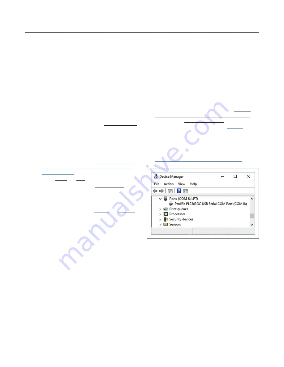
4)  The MAX66301 EV kit uses both the Pro-

lific PL-2303 and a MAXQ610 microcontroller 

to provide SPI or UART connectivity to the 

MAX66301 device. Verify the correct installa-

tion of the virtual COM port by selecting 

Control 

Panel

System

Hardware

Device Manager

 and 

expanding the 

Ports (COM & LPT)

. If the driver is 

installed properly, the Port lists as in 

Figure 1

. Note 

that your COM port number can be different.

5)  Unzip the 

MAX66301-25x_EV_Kit.zip

 in a known 

location. 

Note:

 If you have not already obtained the 

software with this data sheet, request it from  

applications support through the following link:  

http://www.maximintegrated.com/support

.

Figure 1. MAX66301 EV kit Virtual COM Port

Windows is a registered trademark and registered service mark 

of Microsoft Corporation

Summary of Contents for MAX66301-25x

Page 1: ...Ports Power Down Mode by an Input Pin Low Standby Power Antenna Short Circuit Protection Compatible with 3 3V or 5V Supply Voltages Pushbuttons for Board Reset and MAX66301 Reset Port Select Switch C...

Page 2: ...www analog com Analog Devices 2 MAX66301 25x Evaluation Kit Evaluates MAX66301 and MAX66250 MAX66301 25x Evaluation System...

Page 3: ...able 1 and Figure 6 for 3 3V operation b Set the switch SW3 per Table 2 for UART operation when the MAX66301 powers up c Using the USB type A to USB type Mini B cable connect the MAX66301 EV kit s CN1...

Page 4: ...0 6 Open the MAX66301 25x EV kit folder as shown in Figure 2 and double click the setup exe 7 Now double click the Install button as shown in Figure 3 8 The evaluation program GUI appears as shown in...

Page 5: ...www analog com Analog Devices 5 MAX66301 25x Evaluation Kit Evaluates MAX66301 and MAX66250 Figure 4 MAX66301 25x EV Kit GUI...

Page 6: ...standard The AFE in the MAX66301 drives a PCB antenna in a 100mW con figuration Lastly the MAX66250 is the tag in the system supporting authentication i e clone prevention Jumpers and Switches The MA...

Page 7: ...Close 17 18 Close 19 20 Close 21 22 Open 23 24 Link to MAXQ610 UART receive Link to MAXQ610 UART transmit Link to MAXQ610 SPI MISO Link to MAXQ610 SPI MOSI Link to MAXQ610 SPI SCLK Link to MAXQ610 SPI...

Page 8: ...www analog com Analog Devices 8 MAX66301 25x Evaluation Kit Evaluates MAX66301 and MAX66250 Figure 6 MAX66301 EV Kit Jumpers...

Page 9: ...AX66301 during evaluation if needed Table 2 MAX66301 EV Kit Switches Denotes RoHS compliant REFERENCE DESIGNATOR POSITION ON POSITION SIGNAL IS GROUNDED OFF POSITION SIGNAL IS PULLED UP SW1 PUSH 1 Not...

Page 10: ...680PF 50V C0G NP0 0603 C27 CAP0603 3D 1 CL10C681FB8NNNC 820pF CAP CER 820PF 50V NP0 1206 C28 CAP1206 3D 1 12065A821FAT2A 1uF CAP CER 1UF 10V X7R 0603 C31 C32 C41 CAP0603 3D 3 LMK107B7105KA T 3 3uF CAP...

Page 11: ...26 R27 R28 R29 R30 0603 3D 5 ERJ 3EKF22R0V 10K RES ARRAY 6 RES 10K OHM 7SIP RP1 SIP7 3D 1 CSC07A0110K0GEK PUSH SWITCH TACTILE SPST NO 3VA 28V SW1 RESET2 3D 1 HP0315AFKP2 R RESET SWITCH TACTILE SPST NO...

Page 12: ...www analog com Analog Devices 12 MAX66301 25x Evaluation Kit Evaluates MAX66301 and MAX66250 MAX66301 25x EV Kit Schematic Diagram...

Page 13: ...www analog com Analog Devices 13 MAX66301 25x Evaluation Kit Evaluates MAX66301 and MAX66250 MAX66301 25x EV Kit PCB Layout Diagrams...

Page 14: ...www analog com Analog Devices 14 MAX66301 25x Evaluation Kit Evaluates MAX66301 and MAX66250 MAX66301 25x EV Kit PCB Layout Diagrams continued...

Page 15: ...www analog com Analog Devices 15 MAX66301 25x Evaluation Kit Evaluates MAX66301 and MAX66250 MAX66301 25x EV Kit PCB Layout Diagrams continued...

Page 16: ...d MAX66250 MAX66250 EV Kit Bill of Materials MAX66250 EV Kit Schematic Diagram COMMENT DESCRIPTION DESIGNATOR FOOTPRINT QTY PART NUMBER MAX66250 DeepCover Secure Authenticator with ISO 15693 SHA3 256...

Page 17: ...www analog com Analog Devices 17 MAX66301 25x Evaluation Kit Evaluates MAX66301 and MAX66250 MAX66250 EV Kit PCB Layout Diagram continued...

Page 18: ...www analog com Analog Devices 18 MAX66301 25x Evaluation Kit Evaluates MAX66301 and MAX66250 MAX66250 EV Kit PCB Layout Diagram continued...

Page 19: ...CAP0805 3D 1 251R15S220FV4E 56pF CAP CER 56PF 100V NP0 0805 C4 CAP0805 3D 1 08051U560FAT2A 47pF CAP CER 47PF 200V C0G NP0 0805 C5 CAP0805 3D 1 08052U470FAT2A SMA CONN SMA RCPT STR 50OHM EDGE MNT J1 SM...

Page 20: ...www analog com Analog Devices 20 MAX66301 25x Evaluation Kit Evaluates MAX66301 and MAX66250 50 Shielded Antenna PCB Layout Diagrams...

Page 21: ...www analog com Analog Devices 21 MAX66301 25x Evaluation Kit Evaluates MAX66301 and MAX66250 50 Shielded Antenna PCB Layout Diagrams continued...

Page 22: ...www analog com Analog Devices 22 MAX66301 25x Evaluation Kit Evaluates MAX66301 and MAX66250 50 Shielded Antenna PCB Layout Diagrams continued...

Page 23: ...www analog com Analog Devices 23 MAX66301 25x Evaluation Kit Evaluates MAX66301 and MAX66250 50 Shielded Antenna PCB Layout Diagrams continued...

Page 24: ...for its use nor for any infringements of patents or other rights of third parties that may result from its use Specifications subject to change without notice No license is granted by implicationor o...

Reviews: