background image

EVAL-ADUCM420QSP1Z

 User Guide 

UG-1926 


Rev. 0 | Page 11 of 20 

25844-

1

15


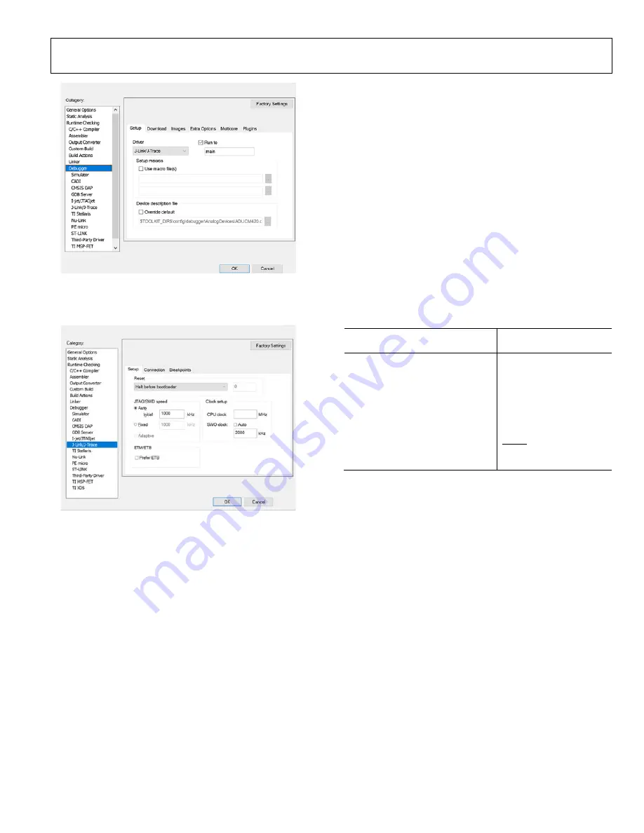
Figure 16. 

J-Link/J-Trace

 Selected in 

Setup

 Tab  

7.


Check that the 

J-Link/J-Trace

 settings in the 

Setup

 tab 

match those as shown in Figure 17.  

25844-

1

16


Figure 17. 

J-Link/J-Trace

 Settings 

8.


Click 

OK,

 and the user can start configuring the example 

program for th

ADuCM420

 in the IAR IDE. 

mIDAS-LINK CONNECTOR—CONNECTING THE 
HARDWARE  

Use the following steps to connect the mIDAS-Link to the 
EVAL-ADUCM420QSP1Z: 
1.


Connect the provided USB cable between the PC and the 
mIDAS-Link connector.  

2.


The yellow LED lights up on the mIDAS-Link to indicate 
the connection to the EVAL-ADUCM420QSP1Z is 
initializing.  

3.


Install the driver for the ADuCM420. Driver installation 
details are included in a 

.exe

 file in the ADuCM420 

installer. 

After connecting the mIDAS-link hardware to the EVAL-
ADUCM420QSP1Z, the mIDAS-Link can be used in 
Keil µVision5 and IAR Embedded Workbench development.  
Table 4 shows the mIDAS-Link pin configuration. 

Table 4. mIDAS-Link Pin Labels  

EVAL-ADUCM420QSP1Z Header 
Pin No.  

mIDAS-Link Pin Labels 

1, 2 

DVDD 

3, 11, 19 

NC 

4, 6, 8,10, 12, 14, 16, 18 

DGND 

P1.0/SIN0 

SWDIO 

SWCLK 

13 

P2.2/SWO option via JP4 

15 

RESET 

17 

P1.1/SOUT1 

EVALUATING THE MDIO DOWNLOAD MODE  

The MDIO downloader can be extracted from the installer on 
the 

ftp://ftp.analog.com/pub/microconverter/ADuCM420


website. Use the MDIO downloader with the 

MDIOWSD


software to download the hexadecimal files. Use the SUB-20 
multiple interface USB adapter (not included) to connect the 
EVAL-ADUCM420QSP1Z to the PC via the 

MDIOWSD


software tool. The Windows 10 Operating System section 
outlines the procedure to download code and the example 
programs from the installer to the ADuCM420 device using the 
MDIO interface. 

Windows 10 Operating System 

After connecting the SUB-20 multiple interface USB adapter to 
the PC, the USB adapter automatically installs the needed SUB-20 
software. To ensure the software properly installs and connects 
to the EVAL-ADUCM420QSP1Z, follow these steps: 
1.


Double click the 

SUB-20 firmware updater.exe

 file 

installed on the PC after the SUB-20 adapter is connected 
to open the graphical user interface (GUI) shown in Figure 18.  


Summary of Contents for EVAL-ADuCM420QSP1Z

Page 1: ...CSP The ADuCM420 development system EVAL ADUCM420QSP1Z is fully packaged to evaluate all features of the ADuCM420 a high precision analog microcontroller The ADuCM420 includes 12 external AINx channel...

Page 2: ...are Installation Procedures 7 Keil Vision5 7 CMSIS Pack in Keil Vision5 8 Library and Project Options for ADuCM420 in Keil Vision5 9 IAR IDE Project Settings 9 mIDAS Link Connector Connecting the Hard...

Page 3: ...CM420QSP1Z User Guide UG 1926 Rev 0 Page 3 of 20 EVAL ADUCM420QSP1Z PHOTOGRAPH UART USB mIDAS Link Digital I Os UART CONNECTOR J LINK CONNECTOR POWER TERMINAL BLOCK 9V WALL WART AINx VDACx 25844 001 F...

Page 4: ...through LDO regulators to regulate the power supply The ADuCM420 can also configure the IOVDD1 and DVDD power supplies to be 1 2 V or 1 8 V and 1 8 V or 3 3 V respectively To configure these supply op...

Page 5: ...Table 2 Power Configurations for the EVAL ADUCM420QSP1Z WLCSP EVAL ADUCM420QSP1Z Optional Jumper Information Jumper Configuration P20 Yes Power selection either via USB power or via Arduino power Pin...

Page 6: ...gle row headers 2 54 mm pitch for example the Samtec SSQ 110 03 G S Figure 3 shows the appropriate connector type For proper slave adapter connection ensure the female part is on the solder side with...

Page 7: ...s the example codes for the ADuCM420 see Figure 5 25844 003 Figure 5 ADuCM420 examples Folder with Projects KEIL VISION5 The Keil Vision5 integrated development environment IDE integrates all the tool...

Page 8: ...the first time it may take a few minutes to update the pack installer 25844 105 Figure 6 Pack Installer 2 After the CMSIS pack installer opens click File Import Select and import the ADuCM420 pack th...

Page 9: ...PROJECT SETTINGS It is recommended for first time users to open an example project from the examples folder For instance the M420_Adc eww file is the IAR Embedded Workbench project file for the ADC e...

Page 10: ...hose shown in the Additional include directories box see Figure 13 25844 112 Figure 13 C C Compiler Setting 5 Next click the Linker category check the Override default box in the Config tab and browse...

Page 11: ...le 4 mIDAS Link Pin Labels EVAL ADUCM420QSP1Z Header Pin No mIDAS Link Pin Labels 1 2 DVDD 3 11 19 NC 4 6 8 10 12 14 16 18 DGND 5 P1 0 SIN0 7 SWDIO 9 SWCLK 13 P2 2 SWO option via JP4 15 RESET 17 P1 1...

Page 12: ...ode to download 25844 009 Figure 19 MDIOWSD GUI 7 To download the code select Program and Verify from the Flash Action box click Start and follow the instructions listed on the GUI Table 5 SUB 20 to E...

Page 13: ...s Erase 8 Repeat Step 4 through Step 7 to select another option from the software tool FLOATING POINT UNIT ENABLE PROCEDURE The settings shown in the Project dropdown menu see Figure 24 are available...

Page 14: ...the FPU example program from the Keil IDE included on the ADuCM420 installer 1 After opening the Keil IDE click the Flash dropdown menu and select the Configure Flash Tools option see Figure 26 25844...

Page 15: ...the settings shown in Figure 28 run the FPU example code from the C Analog Devices ADuCM420 examples M420_FPU folder In debug mode the output Disassembly window displays fractional values of the varia...

Page 16: ...see Figure 32 placed in the IAR folder within the SramMode example program 25844 016 Figure 30 IAR SRAM Setup main c 2 Configure the macros shown in Figure 30 Figure 31 and Figure 32 to run the SRAM m...

Page 17: ...844 020 Figure 34 SRAM Mode sct and s Files 2 By default the M420_SramMode macro uses SRAM Mode 0 The SetSramMode0 s assembly file is added to the subdirectory as shown in Figure 35 Specify which SRAM...

Page 18: ...UG 1926 EVAL ADUCM420QSP1Z User Guide Rev 0 Page 18 of 20 25844 023 Figure 37 Keil SRAM Output Mode 0 25844 024 Figure 38 Flash Configuration Setup...

Page 19: ...ets Flash Address 0x01FFC 0xFFFFFFFF The example code for the ADuCM420 configures Flash Address 0x01FFC 0xFFFFFFFF See page0_checksum in the system_ADuCM420 c file User Flash Pages Corruption of Reser...

Page 20: ...e subject to the following additional limitations Customer shall not i rent lease display sell transfer assign sublicense or distribute the Evaluation Board and ii permit any Third Party to access the...

Reviews: