UG-1635
Rev. 0 | Page 15 of 30
2141
9-
030
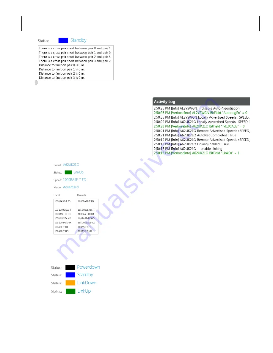
Figure 29. Cable Diagnostics Configuration with Cable Crossed
ACTIVITY WINDOW AND LINKING STATUS
This window displays the current status of the selected PHY
chip (as determined in the
Select Local
section), including
whether a link is established, the speed of the link, and the
speed mode. The local and remote fields show the advertised
speeds available in the local PHY device and also what the
remote PHY is returning (see Figure 30).
If the user switches between two EVAL-ADIN1300FMCZ
boards in the
Select Local
section, the information shown in
these fields will be updated to reflect the information provided
from the board defined as local.
21
419
-03
1
Figure 30. Board Status Information
The GUI displays a color code to show the status of the link
depending on how the user has configured the device (see
Figure 31).
2141
9-
032
Figure 31. GUI Link Status
ACTIVITY LOG INFORMATION SECTION
The activity log reports status information and register write issues
to the selected EVAL-ADIN1300FMCZ board (see Figure 32).
The activity log captures the activity in the GUI corresponding
to the activity on the local PHY, which indicates the various
reads, writes, and information on whether a link is established.
When the frame generator is enabled, this window shows the
frame generator activity. The board identification is recorded
with each bit field change to clarify which device is being
addressed.
21
41
9-
03
3
Figure 32. Activity Log Showing Device Status
To clear the activity log, right click and then click
Clear
. To
export the contents of the activity log for offline review, right
click and then click
Save as
. The file saved is a text file with a
default location in the
Analog Devices
>
ADIN1300
folder.


