background image

UG-AD7175-2 

EVAL-AD7175-2SDZ User Guide 


SOFTWARE OPERATION 


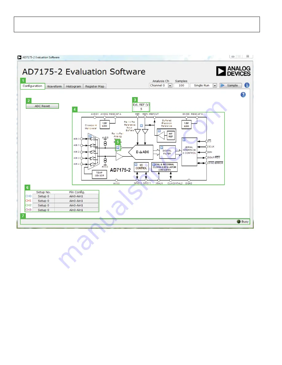
Figure 7. Configuration Tab of th

AD7175-2

 Evaluation Board Software 


OVERVIEW OF THE MAIN WINDOW 

The main window of the software displays the significant 
control buttons and analysis indicators of th

AD7175-2


evaluation board software (see Figure 7). This window is 
divided into four tabs.  

CONFIGURATION TAB (1) 

ADC Reset (2) 

Click 

ADC Reset

 to perform a software reset of th

AD7175-2

There is no hardware reset pin. Perform a hard reset by 
removing power to the board. The software reset has the same 
effect as a hard reset. 

Ext. Ref (3) 

S

ets the external reference voltage used for calculating the 

results on the Waveform and Histogram tabs. The evaluation 
board has an external 5 V ADR445 reference but this can be 

bypassed and so you can change the external reference voltage 
value here to ensure correct calculation of results on the 
Waveform and Histogram tabs. 

Functional Block Diagram (4) 

This is the functional block diagram of the ADC showing each 
of the separate functional blocks within the ADC. Clicking on 
one of the configuration buttons on this graph will open the 
configuration popup window for that block. Not all blocks will 
have a configuration button. 

Configuration Popup Button (5) 

This is one of the configuration popup buttons. Each button 
will open a different window allowing for configuration of the 
relevant functional block. 

Rev. Pr.C | Page 8 of 12 

Summary of Contents for EVAL-AD7175-2SDZ

Page 1: ...port via the system demonstration platform SDP EVAL SDP CB1Z controller board The EVAL AD7175 2SDZ evaluation software fully configures the AD7175 2 device functionality via a user accessible register interface and provides dc time domain analysis in the form of waveform graphs histograms and associated noise analysis for ADC performance evaluation FUNCTIONAL BLOCK DIAGRAM Figure 1 EVAL AD7175 2SD...

Page 2: ...ware 4 Device Description 4 Hardware Link Options 4 Sockets and Connectors 5 Serial Interface 5 Power Supplies 5 Power Supply Configurations 6 Analog Inputs 6 Reference Options 6 Evaluation Board Software 7 Software Installation 7 Launching the Software 7 Software Operation 8 Overview of the Main Window 8 Configuration Tab 1 8 Waveform Tab 8 9 Histogram Tab 19 10 Register Map Tab 22 11 Exiting the...

Page 3: ...P board to the PC via the USB cable For Windows XP you may need to search for the SDP drivers Choose to automatically search for the drivers for the SDP B board if prompted by the operating system 6 Launch the EVAL AD7175 2SDZ software from the Analog Devices subfolder in the Programs menu QUICK START NOISE TEST Use the following procedure to quickly test the noise performance 1 Insert Link LK5 to...

Page 4: ...e external power supply from Connector J3 Position A or J4 Position B LK5 to LK9 Inserted Inserting these links sets up the on board noise test In this mode all inputs short to the common voltage via SL11 SL1 A Sets the voltage applied to the AVDD2 pin Operates using the AVDD1 supply default Position B sets the AVDD2 voltage to 3 3 V supply from the ADP7118 3 3 V U10 regulator SL2 A Selects betwee...

Page 5: ...1 pitch Harwin 20 9990646 FEC 1022255 1 Order codes starting with FEC are for Farnell SERIAL INTERFACE The AD7175 2 evaluation board connects via the serial peripheral interface SPI to the Blackfin ADSP BF527 on the EVAL SDP CB1Z There are four primary signals CS SCLK and DIN all inputs and one output from the ADC DOUT RDY To operate the EVAL AD7175 2SDZ in standalone mode disconnect the evaluatio...

Page 6: ...ct 5 V to J9 at the terminal labeled AVDD 5 Connect 3 3 V to J9 at the terminal labeled IOVDD 6 Connect the 7 V to 9 V input to J5 Set all other links and solder links to the default settings as outlined in Table 1 Split Supply Regulated To set up the board use the following procedure 1 Remove R49 to R51 These links connect AVSS to AGND 2 Insert a zero ohm resistor for R85 3 Set LK1 to Position B ...

Page 7: ... CB1Z Drivers Installation Confirmation Dialog Box After installation is complete connect the EVAL AD7175 2SDZ to the EVAL SDP CB1Z as shown in Figure 2 Connect the EVAL SDP CB1Z board via the USB cable to the computer Follow these steps to verify the SDP B controller board driver is installed and working correctly 1 Allow the Found New Hardware Wizard to run 2 Once the drivers are installed check...

Page 8: ...eference voltage used for calculating the results on the Waveform and Histogram tabs The evaluation board has an external 5 V ADR445 reference but this can be bypassed and so you can change the external reference voltage value here to ensure correct calculation of results on the Waveform and Histogram tabs Functional Block Diagram 4 This is the functional block diagram of the ADC showing each of t...

Page 9: ...f samples gathered per batch and whether only a single batch of multiple batches of samples are gathered This is unrelated to the ADC mode You can capture a defined sample set or continuously gather batches of samples In both cases the number of samples set in the Samples 10 numeric input dictates the number of samples Sample 12 This starts gathering ADC results Results appear in the Waveform Grap...

Page 10: ...after each sample batch CRC Error 17 This LED icon illuminates when a cyclic redundancy check CRC error is detected in the communications between the software and the AD7175 2 The CRC functionality on the AD7175 2 is disabled by default and must be enabled for this indicator to work Noise Analysis 18 This section displays the results of the noise analysis for the selected analysis channel This inc...

Page 11: ... or program the register value directly into the number control on the right Bitfield List 25 This list shown all the bitfields of the register selected in the Register Tree 23 The values can be changed using the drop down menu or directly entering a value into the number control on the right Documentation 26 This field contains the documentation for the register of bitfield selected in the Regist...

Page 12: ...arty for any reason Upon discontinuation of use of the Evaluation Board or termination of this Agreement Customer agrees to promptly return the Evaluation Board to ADI ADDITIONAL RESTRICTIONS Customer may not disassemble decompile or reverse engineer chips on the Evaluation Board Customer shall inform ADI of any occurred damages or any modifications or alterations it makes to the Evaluation Board ...

Reviews: