


UG-1262
Rev. B | Page 86 of 312
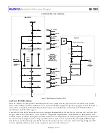
Close SW0 when changing the R
TIA
value, and open SW0 again when the change is complete. If high currents are detected on the low
power TIA input path when using an oxygen electrochemical sensor, close the shorting switch, SW1, to protect the low power TIA input
circuitry. SW1 is controlled by LPTIASWx, Bit 1. For full details of the high speed TIA in Figure 16 and Figure 17, refer to the High Speed TIA
Circuits section.
+
PA
–
SW2
SW13
+
LPTIA
–
SW7
10kΩ
SW3
SW4
SW10
SW8
SW15
RE0
SW6
SW1
SW5
SW0
SW11
R
LOAD
LPTIACON0
[9:5]
LPTIACON0
[12:10]
CE0
RE0
CAP_POT0
SE0
RC0_0
RC0_1
SE0
TSWFULLCON[4]
T5
TSWFULLCON[6]
T7
SE1
VBIAS0
LPDACSW0[3]
OPEN: LPDACCON0[5] = 1
AND LPDACSW0[4] = 0
LPDACCON0[3]
LPDACCON0[4]
VZERO0
VREF_2.5V
AIN4_LPF0
LPTIA0_P_LPF0
FORCE/SENSE
SW14
TO CHANNEL 1
R
LPF
LPTIACON0
[15:13]
SW9
10kΩ
R
TIA
LPDAC0
12-BIT
6-BIT
ULPBUF
ULPREF
SW12
LPDACSW0[1]
LPDACSW0[2]
ADC
MUX
1667
5-
01
6
ADCVBIAS_CAP (1.11V)
LPDACSW1[0]
VZERO1
VZERO0
LPDACSW0[0]
HSTIA
Figure 16. Low Power TIA, Low Power Potentiostat, and Low Power DAC Switches for Channel 0


