


Preliminary Technical
Data
Rev. PrA | Page 44 of 82
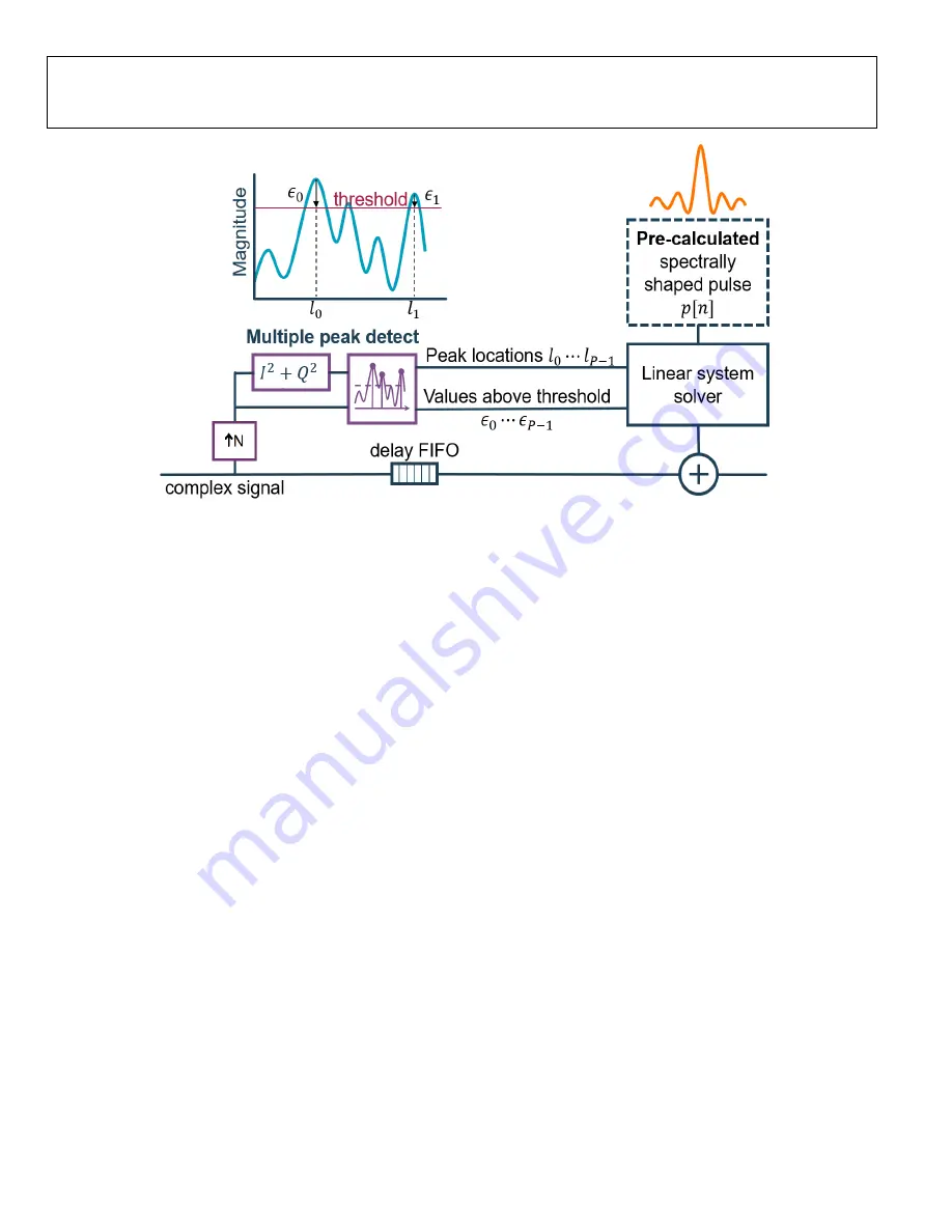
Figure 53. CFR Engine Architecture in ADRV9029
The complex IQ signal (transmitter data) goes into a variable delay FIFO and correction is applied at its output. The input data
also goes into an interpolator, which can interpolate by 1×, 2×, or 4× times the input sample rate. This interpolated data is then
fed into a peak detector. The peak detector determines the location of all the peaks in the signal and the delta by which they
exceed the programmable threshold. This information is then fed into a linear system solver. These peaks can be corrected by
using a pre-computed spectrally shaped pulse (also called correction pulse) which is stored in a pulse RAM. Multiple peaks can
be simultaneously cancelled by time-shifting and combining these spectrally shaped pulses.
The linear system solver calculates the correction coefficients that get combined with the input signal (at the output of the delay
FIFO) to produce an output signal which has a much lower peak-to-average ratio. This corrected output signal is then passed to
two more similar CFR engines to correct missed peaks, as well as peaks that need further correction after passing through the
first engine.
The CFR block within the transceiver consists of three cascaded CFR engines followed by a hard clipper to clip the few peaks that
are skipped by all three CFR engines. At the output of each engine, there exists a mux that can be programmed to bypass CFR or
Error! Objects cannot be created from editing field codes.
Figure 54. ADRV9029 Cascaded CFR Engine Blocks
The Hard Clipper unit at the very end of the CFR block clips any signal above a programmable threshold. This threshold generally
should not be lower than the thresholds used in the CFR engines as it will lead to increase in noise (both in-band and out of
band). Each of the individual units above can be bypassed depending on the use case and desired performance.
The transceiver incorporates the CFR block at the very beginning of the transmitter datapath right after the JESD block. Please
note that the CFR engine can handle a maximum input sampling rate of 245.76 MHz with an internal interpolation up to 4×.
Therefore, the maximum sampling rate for the base and correction pulses is 983.04 MHz.
OVERVIEW OF BLOCKS USED IN CFR
This section provides a brief summary of the major blocks used in each of the CFR engines.