


UG-1828
Preliminary Technical Data
Rev. PrC | Page 128 of 338
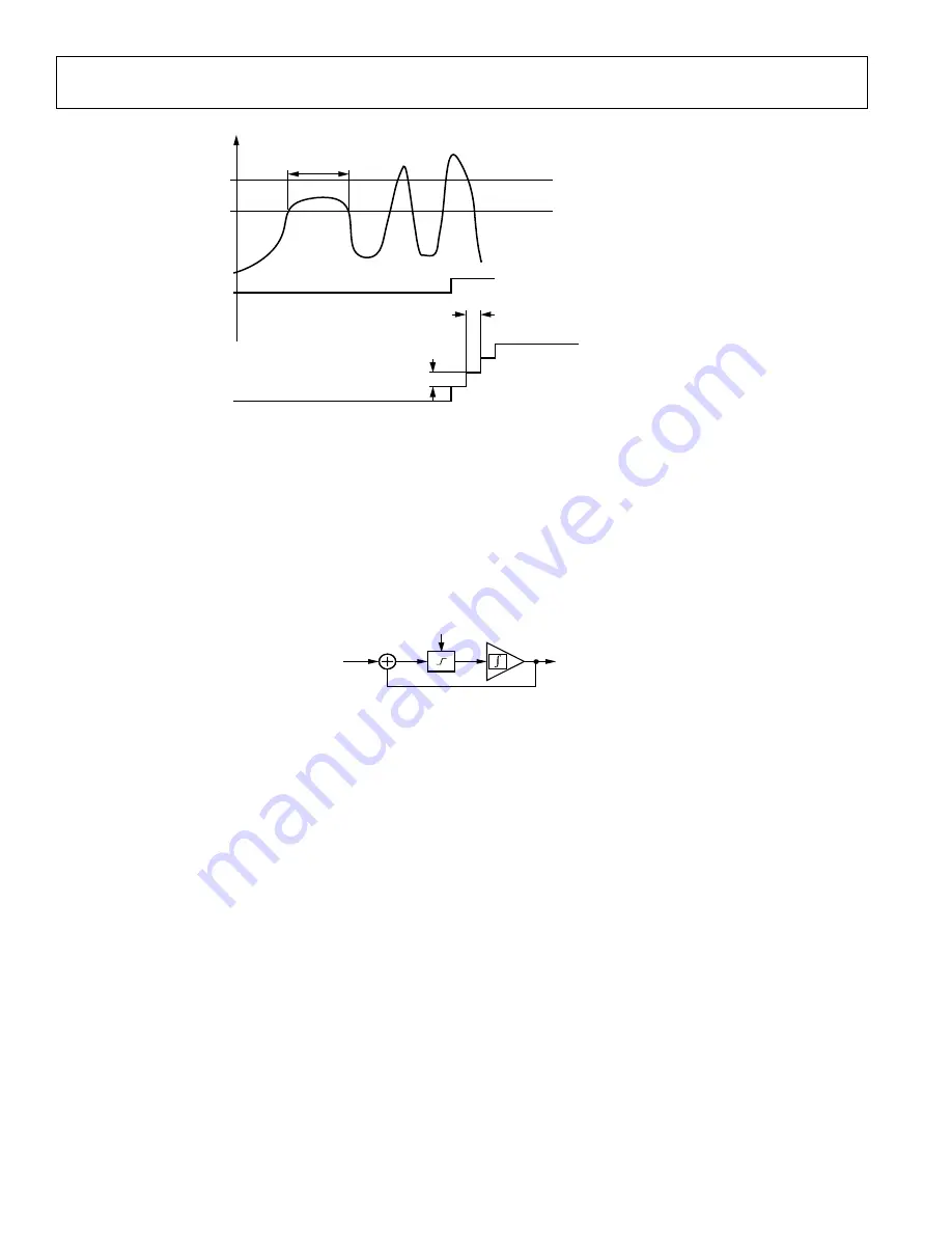
Figure 132. Power Amplifier Monitor
Slew Rate Limiter (SRL)
The slew rate limiter is the other method for power amplifier protection. It essentially limits the rate of change of a waveform by
continuously monitoring the difference between the input and output of the block and limiting the amount the output that can change
during one cycle. As a result, sudden changes in the input will be applied to the output over several cycles or symbols. Through API
commands, the user can control this slew limit as a fraction of full-scale which can be varied from very strong slew limiting to no slew
limiting at all. For example, if the slew limit is set to 10% of full-scale, a full-scale step input to the step limiter results in a ramp which
spreads over the next 10 clock cycles. The basic block diagram of the implemented slew rate limiter is shown in Figure 133. As shown in
this figure, the output sample is looped back to subtract from the input sample to decide the slew rate. Based on the slew limit selection, a
proper scaling factor is applied to reduce the slew rate to the desired level.
Figure 133. Basic Block Diagram of the Slew Rate Limiter
Transmitter QEC
In the analog circuitry of a direct-conversion transmitter, there are 3 major non-idealities which are gain variation between I and Q
datapath, phase imbalance (non-90 degree between LO driving I and Q mixers) and differences in the LPF such as group-delay variations.
Without properly correcting them, the output spectrum of the transmitter could be significantly degraded due to the undesired images.
Transmitter QEC is designed to estimate and correct those non-idealities through initial and tracking calibrations. The initial calibration
is performed by generating a tone through the NCO and inserting it to the transmitter datapath. Note this tone is visible at the transmitter
output therefore user must ensure that antenna is isolated from the transmitter (power amplifier is off) during transmit initial calibration.
Internally in the device, the output from the transmit upconverter is looped to the observation receiver (ORx) through internal loopback
(ILB) path. The ORx output and the transmitted tone are used to estimate the mismatches. Tables are generated to record the initial
calibration results, which could be further refined through tracking calibrations on-the-fly. During signal transmission, the mismatch
estimations are applied in the transmitter datapath so that the non-idealities could be compensated. For more detailed information, refer
to the Transmitter/Receiver/Observation Receiver Signal Chain Calibrations section.
Transmitter LOL
In the transmitter, any coupling of the LO to the RF output or baseband DC offset could generate an undesired tone at the LO frequency.
Without properly correcting it, it could cause a negative impact on the system performance.
Transmitter LOL is designed in the transmit signal chain to handle this problem. Similarly, it estimates the DC offset through initial and
tracking calibrations and then apply the estimation in the baseband to cancel the undesired tone. For more detailed information, refer to
the Transmitter/Receiver/Observation Receiver Signal Chain Calibrations section.
DPD
DPD is an optional feature available in the ADRV9001 device to enable users to achieve higher power amplifier efficiency while still meet
Error Vector Magnitude (EVM) and adjacent channel leakage ratio (ACLR) requirements in their transmitter signal chain for compliance
Tx OUTPUT POWER
PA_PROTECTION_RAMP_MAX_ATTENUATION
PA_PROTECTION_RAMP_STEP_SIZE
PA_PROTECTION_ERROR_FLAG
PA_PROTECTION_AVG_DUR
PEAK THRESHOLD
AVERAGE THRESHOLD
PA_PROTECTION_RAMP_STEP_DURATION
TX_ATTENUATION
24159-
092
SLEW LIMIT
(10, 20, 30, 50) % OF FULL SCALE
IN
–
OUT
24159-
093