UG-1571
User Guide
Rev. 0 | Page 6 of 18
GUI SOFTWARE
OPERATING THE BOARD WITH THE GUI
Before running the software, take the following steps:
1.
Ensure that the USB to I
2
C dongle,
plugged into the PC USB port.
2.
Connect a 5 V power supply between the VBUS and GND
screw terminals (see Figure 17 for a connection diagram).
Or connect a Li-ion battery or battery simulator between
ISOB and GND (see Figure 17).
3.
Click
Start
>
All Programs
>
ADP5360 GUI 1v0
>
ADP5360 GUI
.
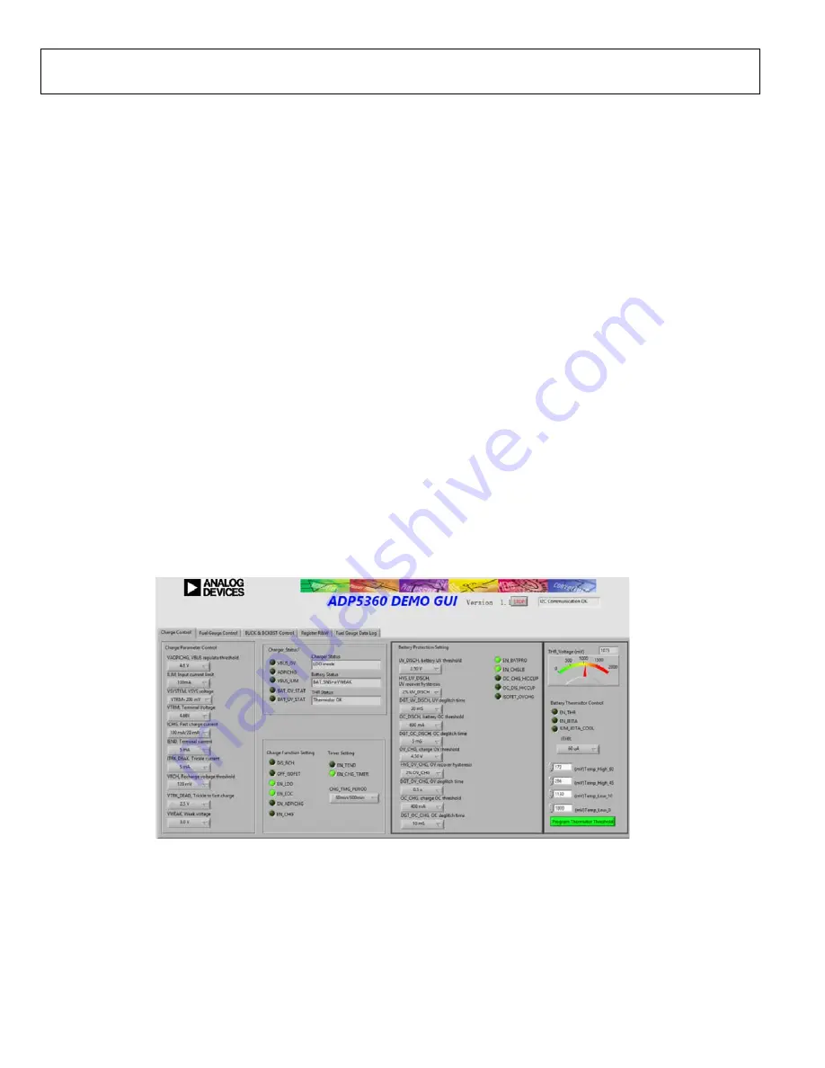
The software is now ready to use, and the window shown in
Figure 10 appears. The GUI software automatically reads the
content of the registers and updates the status of the registers in
real time.
BASIC CHARGING PARAMETER SETTINGS
To start the
charger, adhere to the following steps:
1.
Connect a 5 V power supply between the VBUS and GND
screw terminals. Connect a discharged Li-ion battery or
simulation battery between ISOB and GND (see Figure 17).
2.
The resistance in the thermistor (THR) input corresponds
to a battery temperature between 10°C and 45°C. If the
THR resistance does correspond with the battery
temperature, the
THR Status
, located in the
Charger_Status1
section (see Figure 10), reads
Thermistor OK
. If not, adjust the R4 variation resistor
using a screwdriver to achieve the
Thermistor OK
message
in
THR Status
.
3.
Click
EN_CHG
in the
Charge Function Setting
section
shown in Figure 10 to set the EN_CHG bit high (
EN_CHG
lights up in the GUI) to start the charger.
Charging begins with the default operational parameter settings
when the EN_CHG bit is set high. The options under
Charge
Parameter Control
on the left side of the
Charge Control
tab
can also be selected before the
Besides
Charge Parameter Control
, the
Charge Control
tab
includes other options such as the
Charge
Function Setting
,
Timer Setting
,
Battery Protection Setting
, and
Battery
Thermistor Control
. This tab also indicates the charger status,
battery status, and THR status.
20
603
-010
GUI Software,
Charge Control
Tab


