Evaluation Board User Guide
UG-467
Rev. 0 | Page 3 of 12
EVALUATION BOARD SOFTWARE
INSTALLING
Before installing the
evaluation software, the drivers for
must be installed. The software and the
instructions can be obtained from
After proper installation of the
drivers, insert
Setup.exe
.
USING THE SOFTWARE GUI
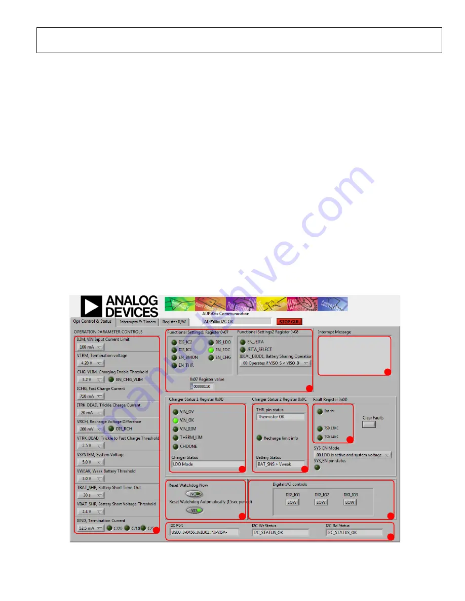
The following are the GUI operation controls and status tools
(see Figure 2):
1.
Operation parameter controls
2.
Functional enables
3.
Interrupt register indicator (Register 0x0A)
4.
Charger status
5.
Battery status
6.
Fault indicators
7.
Watchdog control
8.
Digital I/O controls
9.
I
2
C Communication Status Indicators
OPERATING THE BOARD WITH THE GUI
Complete the following steps to use the board:
1.
Before running the software, ensure that the Analog Devices
is plugged into the USB port of the PC.
2.
Connect a 5 V power supply to VIN_F using the USB
Micro A-to-USB Micro B connector or alternatively connect
the power supply between the VIN_F test point and GND
(see Figure 5).
3.
Click
Start
>
All Programs
>
ADP506x GUI 3Vx SDP
>
ADP506x GUI SDP
. Once this step is completed, the
software is ready to use.
VIN must be above 2.5 V in order for the I
2
C communication of
the
to start working. The VIN voltage level is monitored,
and the indicators are shown in the charger status indicators
(see Number 4 in Figure 2). The GUI automatically reads the
content of the registers after every 0.3 seconds from the last
action and updates the status of the registers on screen.
If there is a problem in the I
2
C communication, the status
indicators show an error message (see Number 9 in Figure 2).
When I
2
C communication is operational, status indicators show
I2C_STATUS_OK
10993-
012
3
2
1
7
4
5
6
8
9
Figure 2.
GUI Operation Control and Status Tab


