ADM1060
Rev. B | Page 32 of 52
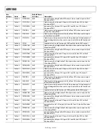
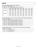
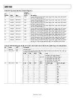
Table 37. Programmable Delay Block (PDB) Registers
Hex
Addr. Table Name
Default
Power-On
Value Description
0C
P1PDBTIM
0x00
Delay for PDB1. Delay for rising edge and falling edge programmed separately.
1C
P2PDBTIM
0x00
Delay for PDB2. Delay for rising edge and falling edge programmed separately.
2C
P3PDBTIM
0x00
Delay for PDB3. Delay for rising edge and falling edge programmed separately.
3C
P4PDBTIM
0x00
Delay for PDB4. Delay for rising edge and falling edge programmed separately.
4C
P5PDBTIM
0x00
Delay for PDB5. Delay for rising edge and falling edge programmed separately.
5C
P6PDBTIM
0x00
Delay for PDB6. Delay for rising edge and falling edge programmed separately.
6C
P7PDBTIM
0x00
Delay for PDB7. Delay for rising edge and falling edge programmed separately.
7C
P8PDBTIM
0x00
Delay for PDB8. Delay for rising edge and falling edge programmed separately.
8C
P9PDBTIM
0x00
Delay for PDB9. Delay for rising edge and falling edge programmed separately.
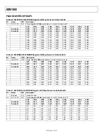
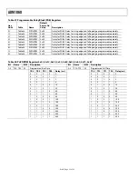
Table 38. PnPDBTIM Registers 0x0C, 0x1C, 0x2C, 0x3C, 0x4C, 0x5C, 0x6C, 0x7C, 0x8C
Bit Name R/W Description
Bit Name R/W Description
7–4
TR3−TR0
W
Programmed Rise Time
3–0
TF3−TF0
W
Programmed Fall Time
TR3 TR2 TR1 TR0 Delay
(ms)
TF3 TF2 TF1 TF0 Delay
(ms)
0 0 0 0 0
0 0 0 0 0
0 0 0 1 1
0 0 0 1 1
0 0 1 0 2
0 0 1 0 2
0 0 1 1 5
0 0 1 1 5
0 1 0 0 10
0 1 0 0 10
0 1 0 1 20
0 1 0 1 20
0 1 1 0 40
0 1 1 0 40
0 1 1 1 60
0 1 1 1 60
1 0 0 0 80
1 0 0 0 80
1 0 0 1 100
1 0 0 1 100
1 0 1 0 150
1 0 1 0 150
1 0 1 1 200
1 0 1 1 200
1 1 0 0 250
1 1 0 0 250
1 1 0 1 300
1 1 0 1 300
1 1 1 0 400
1 1 1 0 400
1 1 1 1 500
1 1 1 1 500

