background image

UG-059 

Evaluation Board User Guide


Rev. 0 | Page 4 of 12 

USING THE USB SOFTWARE 

The evaluation board kit is supplied with a CD containing PC 
software that allows the user to control the evaluation board via 
the USB interface. Note that the software must be installed before 
the evaluation board is connected to the USB port. The software 
installation program usually runs automatically when the CD is 
inserted in the drive; however, if this doesn’t happen, double-
click the 

setup.exe

 file in the root directory of the CD. The soft-

ware is installed, and shortcuts are placed on the start menu in a 
folder called Analog Devices. When the software is installed, 
the evaluation board can be connected to the USB port. 

When the software is started, the user is presented with a 
selection box. The selection box presents a choice of using the 
AD5501 or AD5504. Click the appropriate button for the board 
being used. 

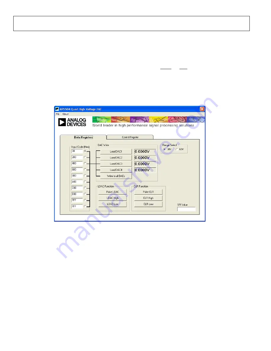
The main control panel for the AD5504 software is shown in 
Figure 2. Use this panel to load values to the DACs and set the 
status of the LDAC and CLR pins. It should be noted that when 
power is first applied to the AD5501/AD5504, the DACs are 
powered down by default. The DACs are powered up by 
selecting the appropriate options in the control register panel. 


0

85

51

-00

2


Figure 2. Main Control Panel 


Summary of Contents for AD5501

Page 1: ...onality of the AD5501 AD5504 evaluation board Use this user guide in conjunction with the AD5501 or AD5504 data sheet as appropriate to evaluate board the functionality and performance of the AD5501 A...

Page 2: ...n 1 Functional Block Diagram 1 Revision History 2 Functionality Overview 3 Safety Requirements 3 Power Supplies 3 DAC Outputs 3 USB Interface 3 Standalone Operation 3 Using the USB Software 4 Schemati...

Page 3: ...e the interface Link LK1 should be inserted STANDALONE OPERATION The evaluation board can be used as a standalone device if required The advantage to this is that it lets the user connect the interfac...

Page 4: ...shortcuts are placed on the start menu in a folder called Analog Devices When the software is installed the evaluation board can be connected to the USB port When the software is started the user is...

Page 5: ...Evaluation Board User Guide UG 059 Rev 0 Page 5 of 12 SCHEMATICS AND ARTWORK 08551 003 Figure 3 Evaluation Board Schematic 1 of 3...

Page 6: ...UG 059 Evaluation Board User Guide Rev 0 Page 6 of 12 08551 004 Figure 4 Evaluation Board Schematic 2 of 3...

Page 7: ...Evaluation Board User Guide UG 059 Rev 0 Page 7 of 12 08551 005 Figure 5 Evaluation Board Schematic 3 of 3...

Page 8: ...shorting shunt FEC 102 2247 and FEC 150 411 2 LK9 LK10 6 pin 3 2 0 1 header and shorting shunt FEC 102 2231 and FEC 150 411 4 R1 to R4 Socket pins 2 FEC 329563 two required 4 R5 R7 R11 R19 Resistor 0...

Page 9: ...9 LK10 6 pin 3 2 0 1 header and shorting shunt FEC 102 2231 and FEC 150 411 1 R1 Socket pins 2 FEC 329563 two required 3 R2 to R4 Not populated FEC 329563 two required 4 R5 R7 R11 R19 Resistor 0603 10...

Page 10: ...UG 059 Evaluation Board User Guide Rev 0 Page 10 of 12 NOTES...

Page 11: ...Evaluation Board User Guide UG 059 Rev 0 Page 11 of 12 NOTES...

Page 12: ...use of evaluation boards Information furnished by Analog Devices is believed to be accurate and reliable However no responsibility is assumed by Analog Devices for its use nor for any infringements of...

Reviews: