


September 2012
L010155
7
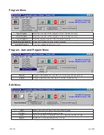
Connector Descriptions - Controller
Slide Switch Descriptions - Controller
Position
Description - Encoder
1
A(-)
2
B(+)
3
IGND - This is an isolated ground for
RS485 only
Position
Description - Limit Switch Inputs
1
+5VDC supply for encoder
2
A channel for encoder
3
B channel for encoder
4
Ground return for encoder
Position
Description - Limit Switch Inputs
1
Home Limit
2
Jog +
3
Jog -
4
Fast Jog
5
Hard Limit +
6
Hard Limit -
7
Soft Limit +
8
Soft Limit -
9
Ground
Position
Description - Motor Connection
1
Input 1 - Analog Input
2
Input 2 - Index on the fly input
3
Input 3
4
Input 4
5
Input 5 - SW2 in position IN5/6
6
Input 6 - SW2 in position IN5/6
7
Ground
Position
Description - Outputs
1
Output 1 - Output on the fly output
2
Output 2
3
Output 3
4
Output 4
5
Output 5
6
Output 6
7
Output 7
8
Output 8 - Encoder Retries Error Output
Switch
Description
P1
This connector is for the RS-232 communication and is labeled RS-232.
J1
This connector is for the thumbwheel module and is labeled TWS.
Switch
Description
SW1
This switch is used to select either RS232 or RS485.
SW2
This switch is used to select either the thumbwheel or inputs 5 and 6.
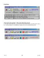
Terminal Descriptions - Controller
Motor Ground
Meant to be used in conjunction with the motor cable ground wire. Make sure the connection is
only on one end of the motor cable ground wire. If no motor shield is available, and if the motor
has no ground wire, the motor ground pin can be left with no connection.
July 2018