System Installation
23
TPI-PRO (Total Presentation Interface)
2.
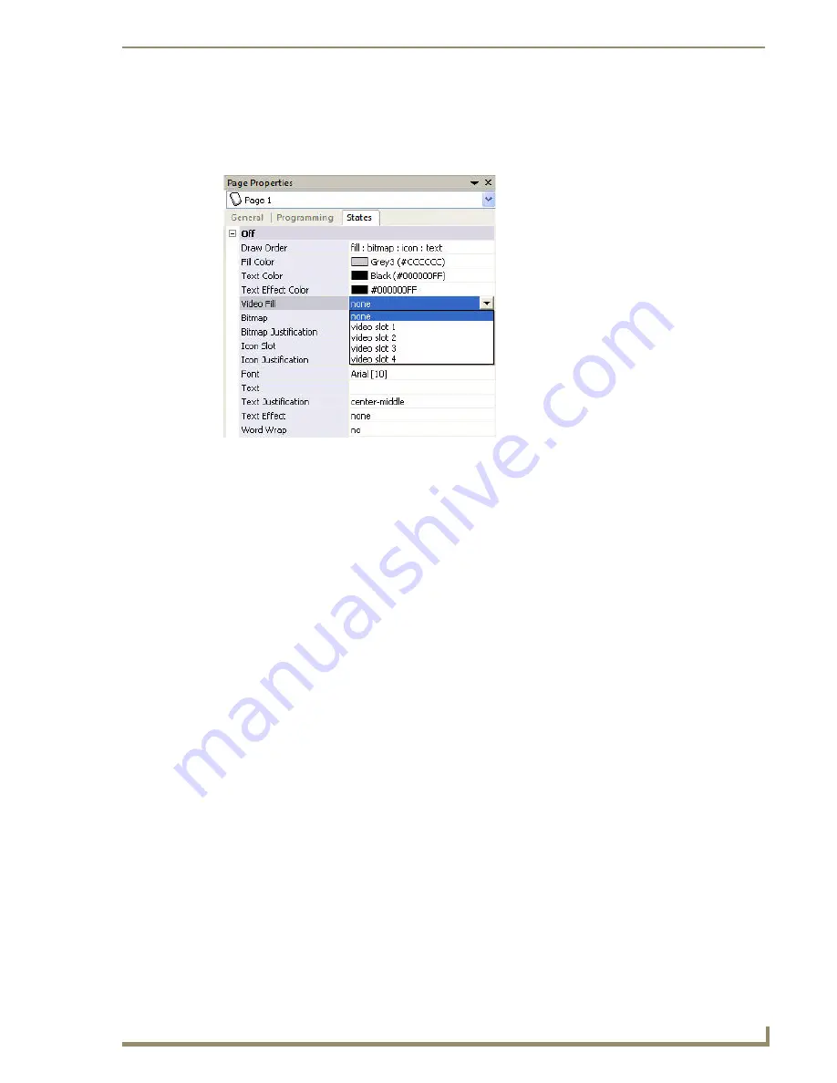
Open the drop-down menu for the
Video Fill
property, and select the
video slot (1-4)
that will be used on
the TPI-PRO.
The example shown in FIG. 27 indicates that only Input 1 is being used - in this case you would select
Video Slot 1
With Video Pass-Thru enabled, the panel's touch coordinates are passed as USB commands from the HD-15
connector on a TPI-PRO to the connected PC. This feature works only if the HD-15 connector is connected
directly to the PC via the HD-15 port on the rear of the TPI-PRO.
The touch coordinates are scaled to fit the resulting window. This allows you to "synch" the touch actions from
the panel to those on the connected computer.
PC control can be established by routing the Mouse and touch monitor input control through the TPI-PRO. In
this scenario, the TPI-PRO is virtually non-existent and is akin to connecting the touch monitor and mouse
directly to the rear of the PC. The PC views the TPI-PRO and the HD-15 and USB connectors as an adapter
connected to a USB mouse device.
This method allows for both mouse and touch monitor input control of the PC (as seen in FIG. 27).
Follow these steps to configure the TPI-PRO to use a touch monitor for touch and mouse pass-thru control of a
PC:
1.
Discharge any acquired static electricity by touching a grounded metal object; disconnect the incoming
power connector from the rear of the TPI-PRO.
2.
Connect a USB mouse to one of the Type-A USB ports on the front or rear of the TPI-PRO.
3.
Connect a USB cable from a USB port on the PC to one of the Type-B USB ports on the rear of the
TPI-PRO (labelled SOURCE KEYBOARD/MOUSE)
.
4.
Connect a video output on the PC to the VIDEO/VGA Input connector on the rear of the TPI-PRO that
corresponds to the Type-B USB port to which the PC is connected. For example:
If the PC is connected to Type-B USB port #1, then the video output on the PC must be connected
to INPUT 1.
If the PC is connected to Type-B USB port #2, then the video output on the PC must be connected
to INPUT 2.
If the PC is connected to Type-B USB port #3, then the video output on the PC must be connected
to INPUT 3 (inputs 3 & 4 available only on the TPI-PRO-4).
If the PC is connected to Type-B USB port #4, then the video output on the PC must be connected
to INPUT 4 (inputs 3 & 4 available only on the TPI-PRO-4).
5.
Connect the touch monitor’s touch (keyboard/mouse) connector to the TPI-PRO:
Depending on the compatibilities of the touch monitor, they can connect to either the TOUCH INPUT
(DB9) connector or one of the Type-A USB ports (labelled KEYBOARD/MOUSE) on the TPI-PRO.
FIG. 28
TPDesign4 - Video Fill drop-down menu
Summary of Contents for TPI-PRO-4
Page 14: ...xii TPI PRO Total Presentation Interface Table of Contents ...
Page 76: ...TPI PRO DVI Configuration Pages 70 TPI PRO DVI Total Presentation Interface ...
Page 172: ...Terminal Telnet Commands 166 TPI PRO DVI Total Presentation Interface ...
Page 180: ...Upgrading Firmware 174 TPI PRO DVI Total Presentation Interface ...
Page 208: ...Supported Input and Output Modes 202 TPI PRO DVI Total Presentation Interface ...
Page 214: ...Appendix 208 TPI PRO DVI Total Presentation Interface ...
Page 217: ...Troubleshooting 203 TPI PRO Total Presentation Interface ...


