

© 2015 Harman. All rights reserved. Solecis, NetLinx, Enova, AMX, AV FOR AN IT WORLD, and HARMAN, and their respective logos are
registered trademarks of HARMAN. Oracle, Java and any other company or brand name referenced may be trademarks/registered trademarks
of their respective companies.
AMX does not assume responsibility for errors or omissions. AMX also reserves the right to alter specifications without prior notice at any time.
The AMX Warranty and Return Policy and related documents can be viewed/downloaded at www.amx.com.
3000 RESEARCH DRIVE, RICHARDSON, TX 75082 AMX.com | 800.222.0193 | 469.624.8000 | +1.469.624.7400 | fax 469.624.7153
AMX (UK) LTD, AMX by HARMAN - Auster Road, Clifton Moor, York, YO30 4GD United Kingdom • +44 1904-343-100 • www.amx.com/eu/
93-1010-315 REV: D
Last Revised: 7/30/2015
Toggling Between DHCP and Static IP Addresses
Solecis Digital Switchers support both DHCP and static IP addresses. When the #3 DIP
switch is set to ON, the switchers automatically use DHCP with link-local fallback.
However, you can use a static IP address which you can set via a Telnet command (SET
IP), or you can use the factory default static IP address. The default static IP address
can be recalled at any time by resetting the unit to its factory default configuration. The
default link-local address is 169.254.2.2. The switcher defaults to the link-local address
if no IP address is obtained from a DHCP server.
The ID Pushbutton can be used to toggle between the DHCP and Static IP Modes.
Perform these steps to toggle between IP addressing modes:
1.
After the switcher boots, press and hold the ID Pushbutton until the STATUS and
LINK/ACT LEDs toggle back and forth in unison approximately 10 times.
2.
Release the pushbutton when the LEDs start to blink faster.
• When you release the Pushbutton, the switcher toggles either from static to
dynamic (DHCP) IP addressing or vice versa and remains in that mode until the
you use ID Pushbutton to toggle the IP mode again or you perform a factory
reset.
• The switcher automatically reboots to complete the process.
Assigning a Device Address (ID Mode)
You can use the ID Pushbutton in conjunction with the ID (Identify) Mode feature in
NetLinx Studio. A momentary press of the ID Pushbutton assigns a device address to
the switcher (which must be bound to the Master). You must first place the device in ID
Mode in NetLinx Studio or the momentary press will be ignored.
NOTE: The latest version of NetLinx Studio is available to download and install from
www.amx.com. Refer to the NetLinx Studio online help for instructions on using the
application.
Perform these steps to assign a device address:
1.
Check to be sure DIP switch #3 on the switcher is set to ON.
2.
In NetLinx Studio’s OnLine Tree, select the Master to which the switcher is bound.
3.
From the Diagnostic menu, select
Device Addressing
. The Device Addressing
dialog box opens.
4.
In the ID Mode section, enter the Device and System numbers that you want
assigned to the device in the appropriate text boxes.
5.
Click
Start Identify Mode
to place the named system in ID Mode. The button
changes to “Cancel Identify Mode” (click to cancel ID Mode). The text box below
the button displays a “Waiting...Press Cancel to Quit” message.
NOTE: When in ID Mode, the entire system is put on hold while it waits for an event from
any NetLinx device in the named system (e.g., pressing the ID Pushbutton on the
switcher). The device that generates the first event is the device that will be “identified.”
6.
Briefly press and release the ID Pushbutton on the switcher. The switcher will
exhibit the following behavior:
• Respond with an ID Mode address response.
• Report its old address offline.
• Report its new address online.
The Online Tree will refresh to display the new device address for the switcher.
NOTE: NetLinx Studio (v3.3 or later) provides the ability to auto-increment IP Addresses
and Hostnames as well as Device and System Numbers. Refer to the NetLinx Studio online
help for details.
Restore the Factory Firmware Image and Factory Default Parameters
During power up
– if you hold the ID Pushbutton until the STATUS and LINK/ACT LEDs
toggle back and forth in unison approximately 30 times (10 slow, 20 fast) and then
release the pushbutton when the LEDs turn solid, the switcher’s factory firmware image
will be restored. This procedure affects both the firmware version and the parameters.
Perform these steps to restore the factory firmware image and factory default
parameters:
1.
Press and hold the ID Pushbutton while plugging in the power connector. Start
counting when the STATUS and LINK/ACT LEDs begin to flash in unison, not when
the power connector is inserted.
2.
After the LEDs complete the following sequence, release the ID Pushbutton:
• Once the switcher has started booting up, all LEDs flash in unison at the rate of
once per second.
• After 10 flashes at that rate, the LEDs will blink in unison at a faster rate.
• After 10 seconds of flashing at the increased rate, all LEDs turn on solid.
3.
Upon release of the ID Pushbutton, the switcher executes the following actions:
• Restores itself to its factory firmware image.
• Resets to factory default parameters
4.
Once all actions in Step 3 are completed, the LEDs all turn off, indicating the
switcher is ready to reboot.
The switcher automatically reboots to complete the process.
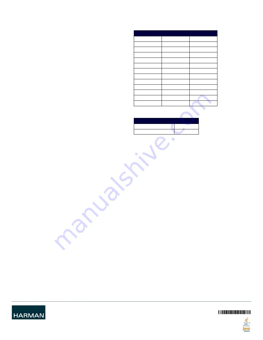
Hardware Information
This section lists important hardware information for the SDX-510M-DX.
Port Numbers
Default IP Addresses
The default IP addressing mode is DHCP.
Important Twisted Pair Cabling Requirements and Recommendations
The following requirements and recommendations apply to cabling DXLink (RJ-45)
connectors:
• DXLink cable runs require shielded category cable (STP) of Cat6 (or better).
• DXLink twisted pair cable runs for DXLink equipment shall only be run within a
common building.*
• DXLink delivers 10.2 Gb/s throughput over shielded category cable. Based on this
bandwidth requirement, we recommend following industry standard practices
designed for 10 Gigabit Ethernet when designing and installing the cable
infrastructure.
• The cables should be no longer than necessary to reach the endpoints. We
recommend terminating the cable to the actual distance required rather than
leaving any excess cable in a service loop.
For more details and helpful cabling information, reference the white paper titled
"Cabling for Success with DXLink" available at
www.amx.com
or contact your AMX
representative.
* "Common building" is defined as: Where the walls of the structure(s) are physically
connected and the structure(s) share a single ground reference.
SDX-510M-DX PORT NUMBERS
Port
Port Number
Address
HDMI IN 1
1
<DevID>:1:0
HDMI IN 2
2
<DevID>:2:0
VGA IN 3
3
<DevID>:3:0
HDMI IN 4
4
<DevID>:4:0
VGA IN 5
5
<DevID>:5:0
HDMI OUT
1
<DevID>:1:0
DXLINK OUT
1
<DevID>:1:0
USB Device
12
<DevID>:12:0
USB Host
13
<DevID>:13:0
External Buttons
14
<DevID>:14:0
AXLINK Keypad 1
15
<DevID>:15:0
AXLINK Keypad 2
17
<DevID>:17:0
SDX-510M-DX DEFAULT IP ADDRESSES
Static IP Address
192.168.1.2
Link-Local Address
169.254.2.2