

QUICK START GUIDE
SDX-510M-DX
Solecis
®
Digital Switcher
Overview
This guide pertains to the SDX-510M-DX 5x1 Multi-Format Digital Switcher with
DXLink Output (
FG1010-315
). The purpose of this document is to illustrate how the
device is to be installed and set up in its simplest configuration by a trained
technician.
Additional Documentation
Additional documentation for this device is available at www.amx.com. Refer to the
Solecis SDX Digital Switchers Instruction Manual
for additional details on installing,
upgrading, and wiring the SDX-510M-DX.
You can also access this Quick Start Guide online by using your mobile device to scan
the QR code located on the bottom of the switcher.
What’s in the Box?
The following items are included with the SDX-510M-DX:
• (2) 5-pin Phoenix connectors
• (1) 4-pin Phoenix connector
• (1) 3-pin Phoenix connector
• (4) rubber feet
• (1) universal power cord
Power
Active power requirements:
• Voltage, AC (typical): 110-240VAC, 50-60 Hz
• Power consumption (max): 110V, 60Hz = 59W; 240V 50Hz = 68W
Environmental Requirements
The environmental requirements for the SDX-510M-DX are as follows:
•
Operating Temperature
: 32° F (0° C) to 104° F (40° C)
•
Storage Temperature
: -4° F (-20° C) to 158° F (70° C)
•
Operating Humidity
: 5% to 85% RH (non-condensing)
•
Storage Humidity
: 0% to 90% RH (non-condensing)
Configuration
Perform the following to prepare the switcher for network communication:
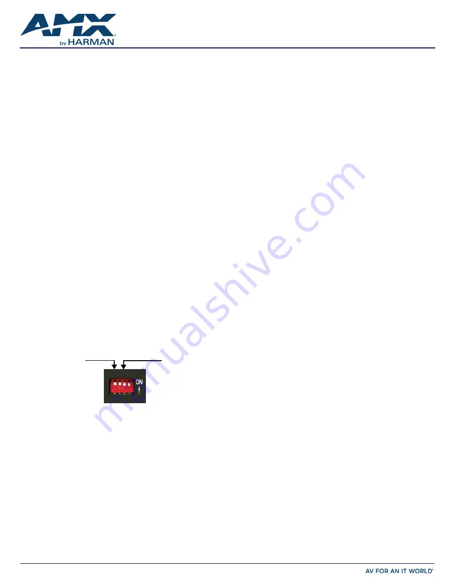
Setting the Configuration DIP Switches
Use the Configuration DIP switch to enable/disable the LAN ports and set network
connectivity. DIP switch settings are read on reboot. Any changes to the DIP switch
settings are not acted upon until after you reboot the device.
Enabling the LAN 10/100 Ports
The LAN 10/100 ports on the switchers are disabled by default. You can enable the
ports by setting #1 DIP switch to ON (see FIG. 1).
Enabling Network Connectivity
Network connectivity on the switchers is disabled by default. You can enable network
connectivity by setting #3 DIP switch to ON (see FIG. 1).
FIG. 1
CONFIGURATION DIP SWITCH
Installation
Before connecting the switcher to its peripheral devices and powering the device, be
sure to mount the device using one of the methods detailed below. You can also
pole-mount the switcher using the V Style Single Module Pole Mounting Kit (
FG1010-
723
). The switchers also include rubber feet that you can apply to the bottom of the
device for table-top mounting.
Surface Mounting
The Solecis Digital Switchers can be mounted using V Style Surface Mounting
Brackets (
FG1010-722
). The Surface Mount Brackets are designed for mounting a
single module (to a wall, on or under a desk, etc.) The brackets may be attached to
mount the top or the bottom flush with the mounting surface.
Rack Mounting
You can mount the switcher on a rack shelf by using an NMX-VRK V-Style Rack Shelf
(
FG3201-60
). In addition to the switcher, you can also use wire ties to mount the
switcher’s power supply on the rack shelf.
1.
Invert the switcher and the rack shelf for ease of installation.
2.
Attach the rack shelf to the bottom of the switcher using the #4-40 3/16 inch
undercut flat head screws (provided). Insert the screws through the underside
of the rack shelf and into the holes on the bottom of the switcher. Note that
only two screws are required.
3.
Install the rack shelf in a standard EIA 19 in. (48.26 cm) rack and secure with
rack-mounting screws.
4.
(This step is optional.) Attach fill plates using the #4-40 3/16 inch undercut
flat head screws (provided). Be sure to use the screw holes closest to the front
of the tray.
Getting Connected
The following sections describe how to connect your switcher to your network,
audio/video sources, and accessories.
Connecting the Switcher to a Video Input
The two GROUP INPUTS areas on the rear panel each feature an HDMI port, a 15-pin
VGA port, a 1/8" mini-Stereo jack, and a 5-pin 3.5mm Dual External Button/LED
Control connector. The HDMI input supports a digital audio/video source. The VGA
input port supports analog video. Use the 1/8" mini-Stereo jack for analog audio.
Though these two sets of input ports support separate digital and analog video
sources, you can only select one input at a time to be sourced to the output ports.
Use the first external button LED control connector to cycle through the inputs
within a particular group. HDMI INPUT 1 is always the first input on both groups.
Group 1 contains inputs 1, 2, and 3. Group 2 contains inputs 1, 4, and 5. You can
route the audio/video from one input within a group at a time. You can cycle through
the inputs in each group by clicking a single button module connected to the
External button connector located next to HDMI INPUT 1 on the rear panel of the
device.
Connecting the Switcher to a Video Output
The switchers can transmit a signal simultaneously to both DXLink and HDMI
outputs.
• The switcher uses standard HDMI cabling to connect to the HDMI inputs and
outputs. Use an HDMI cable to connect the HDMI OUT port on the front panel
of the switcher to the display device.
• The switcher uses category cabling to connect to the DXLink output. See the
Important Twisted Pair Cabling Requirements and Recommendations
section for
information about cable requirements for the DXLink port. Use category
cabling to connect the DXLINK port on the front panel of the switcher to the
DXLink input port on a DXLink receiver, Enova DVX switcher, or Enova DGX
switcher.
Applying Power
Once you have mounted the switcher, set the DIP switches, and connected the
appropriate input and output devices to the ports on the switcher, apply power by
connecting the universal power cord supplied with the switcher.
Video Switching
Auto Switching mode is the default switching mode. With Auto Switching mode, the
switcher responds to the most recently added video input by switching the new input
to display on the HDMI and DXLink output. If the currently selected video source is
removed, the switcher switches to the PC-IN input. If the PC-IN input is removed, the
switcher remains on the PC-IN input.
You can disable Auto Switching mode by using the VIDIN_AUTO_SELECT NetLinx
command. See the
Solecis SDX Digital Switchers Instruction Manual
for more
information on this command.
To switch between video inputs that have already been established, you can perform
one of the following:
• Use the Select button on the front of the panel to toggle through the video
inputs.
• Use a connected external button (not included) with the External Button/LED
Control connector (#1) located on the rear panel of the switcher (to the left of
HDMI IN 1). Each external button press provides the same functionality as the
Select button on the front of the panel.
• The switcher has two sets of groups in which you can use an external button/
LED control connector to cycle through the inputs within a particular group.
Group 1 contains inputs 1, 2, and 3. Group 2 contains inputs 1, 4, and 5. For
group 1, connect the single button module to contact closure 2. For group 2,
connect the single button module to contact closure 4.
#1 switch, set to ON
to enable
LAN 10/100 ports
#3 switch, set to ON
to enable network
connectivity