

For full warranty information, refer to the AMX Instruction Manual(s) associated with your Product(s).
2/10
©2010 AMX. All rights reserved. AMX and the AMX logo are registered trademarks of AMX.
AMX reserves the right to alter specifications without notice at any time.
3000 RESEARCH DRIVE, RICHARDSON, TX 75082 • 800.222.0193 • fax 469.624.7153 • technical support 800.932.6993 • www.amx.com
93-2262-40
REV: B
1.
ETHERNET/POE Port on the NXD-43X
: Connect the RJ45 connector inside
the Table-Top Stand to the ETHERNET/POE port on the side panel of the
NXD-43X.
2.
USB Port on the NXD-43X:
Connect the USB connector inside the
Table-Top Stand to the USB port on the side panel of the NXD-43X.
Step 5: Install The NXD-43X Into the Table-Top Stand
At this point the touch panel can be installed in the TTS enclosure:
1.
Slide the touch panel into the Table-Top Stand until the front of the panel sits
flush against the front panel of the Table-Top Stand.
Note
: Be careful not to pinch or otherwise damage the cables connecting the
NXD-43X to the internal connectors in the Table-Top Stand.
2.
Use the two mounting screws (included with the Table-Top Stand) to secure the
touch panel to the Table-Top Stand enclosure (FIG. 6).
Note
: Do not use excessive force or over-tighten the screws - doing so could damage
the touch panel.
Step 6: Re-Install the Bezel on the NXD-43X
The Bezel snaps on and off the NXD-43X, no screws are used or required.
To re-install the Bezel on the NXD-43X:
1.
Connect the button cable from the panel to the button cable connector on the
inside of the Bezel (FIG. 7).
2.
Carefully align the Bezel with the front of the NXD-43X panel.
•
Note the positions of the tabs on the top-front edge of the Table-Top Stand (see
FIG. 7), and the corresponding tabs on the inside (top-front edge) of the Bezel.
Note
: Make sure to align the Light, and PIR Motion sensor locations to their
respective openings on the Bezel.
3.
Gently press the top edge of the Bezel onto the top edge of the Table-Top Stand,
and engage the metal tabs on the Table Top Stand with the matching notches on
the Bezel.
4.
Gently press the bottom edge of the Bezel on to the bottom edge of the Table-
Top Stand until it snaps into place.
Step 7: Install the Bezel on the NXA-TTS43X-BL
The final step is to install the Bezel on the Table-Top Stand: the Bezel slides onto the
Table-Top Stand from the rear.
Slide the Bezel on to the NXA-TTS43X-BL, from the rear of the enclosure, until it
snaps into place on the Table-Top Stand.
FIG. 8 provides an exploded view of the entire assembly including the NXA-43X Bezel,
Panel, Table-Top Stand and NXA-TTS43X-BL Bezel:
NXA-TTS43X-BL Rear Panel Connectors
Use the rear panel connectors on the NXA-TTS43X-BL to connect the touch panel to
the control system. Once connected, these connectors behave exactly the same as
the ETHERNET/POE and USB ports on the touch panel itself.
Secure Mounting / Alternate Cable Routing
The NXA-TTS43X-BL features a cable routing knockout on the bottom panel,
mounting holes and internal strain relief to provide a secure table-top installation
option (FIG. 9).
Refer to the
TTS Secure Mounting / Alternate Cable Routing Installation Guide
(available at www.amx.com) for instructions.
Additional Documentation
Refer to the NXD-430/435 Operation/Reference Guide (available at ww.amx.com) for
details on wiring and connection information for the NXD-43X panels.
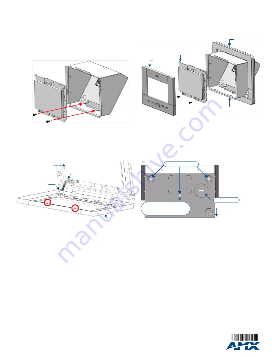
FIG. 6
Inserting the NXD-43X into the NXA-TTS43X-BL - secure with 2 mounting screws
FIG. 7
Button Connector location (Inside Bezel)
NXD-43X
Panel
NXA-TTS43X-BL
mounting screws
NXD-43X Panel
Button Connector
Button Connector Cable
NXD-43X
Bezel
(front)
Tab
Tab
FIG. 8
Installing the Bezel on the Panel/Table-Top Stand assembly
FIG. 9
Bottom Panel (Alternate Cable Routing)
NXA-TTS43X-BL
NXD-43X
Table-Top Stand
Bezel
Bezel
NXD-43X
Panel
(rear)
Surface Mounting holes are
beneath the rubber feet
Surface Mounting holes
Cable knockout
The Strain Relief Bracket
(mounted inside the enclosure)
also uses this mounting hole


