

For full warranty information, refer to the AMX Instruction Manual(s) associated with your Product(s).
3/11
©2011 AMX. All rights reserved. AMX and the AMX logo are registered trademarks of AMX.
AMX reserves the right to alter specifications without notice at any time.
3000 RESEARCH DRIVE, RICHARDSON, TX 75082 • 800.222.0193 • fax 469.624.7153 • technical support 800.932.6993 • www.amx.com
93-2178-62
REV: D
For each attached 802.3af-compliant device, the switch automatically senses the load and
dynamically supplies the required power. Independent overload and short-circuit protection
for each port allows the switch to automatically shut down a port’s power when limits are
exceeded. Port 1 on the switch can provide up to 25 W of power to an attached device at the
standard 48 DC voltage. Ports 2-8 can provide up to 15.4 W of power.
Installing the NXA-ENET8PoE
For more information on installing and configuring the NXA-ENET8PoE, please refer to the
NXA-ENET8PoE Operation Reference Guide
, available at
www.amx.com
.
Selecting a Site
NXA-ENET8PoE units can be mounted in a standard 19-inch equipment rack or on a flat
surface. Be sure to follow the guidelines below when choosing a location.The site should:
•
Be at the center of all the devices you want to link and near a power outlet.
•
Be able to maintain its temperature within 0 to 45 °C (32 to 113 °F) and its humidity
within 10% to 90%, non-condensing.
•
Provide adequate space (approximately five centimeters or two inches) on all sides for
proper air flow.
•
Be accessible for installing, cabling and maintaining the devices.
•
Allow the status LEDs to be clearly visible.
Make sure twisted-pair cable is always routed away from power lines, fluorescent lighting
fixtures, and other sources of electrical interference, such as radios and transmitters.
Make sure that the unit is connected to a separate grounded power outlet that provides 100
to 240 VAC, 50 to 60 Hz, is within 2 m (6.6 feet) of each device and is powered from an
independent circuit breaker. As with any equipment, using a filter or surge suppressor is
recommended.
Ethernet Cabling
To ensure proper operation when installing the switches into a network, make sure that the
current cables are suitable for 10BASE-T, 100BASE-TX or 1000BASE-T operation. Check
the following criteria against the current installation of your network:
•
Cable type: Unshielded twisted pair (UTP) or shielded twisted pair (STP) cables with
RJ-45 connectors; Category 3 or better for 10BASE-T, Category 5 or better for
100BASE-TX, and Category 5, 5e or 6 for 1000BASE-T.
•
Protection from radio frequency interference emissions
•
Electrical surge suppression
•
Separation of electrical wires (switch related or other) and electromagnetic fields from
data-based network wiring
•
Safe connections with no damaged cables, connectors or shields
Installing an Optional SFP Transceiver
The NXA-ENET8PoE supports the following optional transceivers:
•
1000BASE-SX
•
1000BASE-LX
•
1000BASE-LH
To install an SFP transceiver:
1.
Consider network and cabling requirements to select an appropriate transceiver type.
2.
Insert the transceiver with the optical connector facing outward and the slot connector
facing down. Note that SFP transceivers are keyed so they can only be installed in one
orientation.
3.
Slide the transceiver into the slot until it clicks into place.
Note:
SFP transceivers are hot-swappable. The switch does not need to be powered off
before installing or removing a transceiver. However, always first disconnect the network
cable before removing a transceiver.
Note:
SFP transceivers are not provided.
Connecting to a Power Source
To connect the NXA-ENET8PoE to a power source:
1.
Insert the power cable plug directly into the socket located at the back of the device.
2.
Plug the other end of the cable into a grounded, three-pin, AC power source.
Note:
For international use, you may need to change the AC line cord. You must use a line
cord set that has been approved for the socket type in your country.
3.
Check the front-panel LEDs as the device is powered on to be sure the Power LED is
on. If not, check that the power cable is correctly plugged in.
Connecting Network Devices
The NXA-ENET8PoE units are designed to interconnect multiple segments (or collision
domains). It can be connected to network cards in PCs and servers, as well as to hubs,
switches or routers. It may also be connected to devices using optional SFP transceivers.
If 802.3af-compliant PoE devices are connected to the NXA-ENET8PoE’s 10/100 Mbps
ports, the device automatically supplies the required power.
Power over Ethernet Connections
The NXA-ENET8PoE automatically detects an 802.3af-compliant device by its authenticated
PoE signature and senses its required load before turning on DC power to the port. This
detection mechanism prevents damage to other network equipment that is not 802.3af
complaint.
Note:
Power-over-Ethernet connections work with all existing Category 3, 4, 5, 5e or 6
network cabling, including patch cables and patch-panels, outlets, and other connecting
hardware, without requiring modification.
The NXA-ENET8PoE delivers power to a device using wire pairs in the connecting Ethernet
cable. The switch can provide up to 15.4 W of power continuously on each 10/100 Mbps port.
However, taking into account some power loss over the cable run, the amount of power that
can be delivered to a terminal device is 12.95 W. If a device draws more than 15.4 W, from a
port, an overload condition occurs and the port turns off the power.
The NXA-ENET8PoE controls the power and data on a port independently. Power can be
requested from a device that already has a data link to the switch. Also, the NXA-ENET8PoE
can supply power to a device even if the port’s data connection has been disabled. The
power on a port is continuously monitored by the switch and it will be turned off as soon as a
device connection is removed.
Connecting to PCs, Servers, Hubs and Switches
To connect to a PC, server, hub, or switch:
1.
Attach one end of a twisted-pair cable segment to the device’s RJ-45 connector.
2.
If the device is a PC card and the NXA-ENET8PoE is in the wiring closet, attach the
other end of the cable segment to a modular wall outlet that is connected to the wiring
closet. Otherwise, attach the other end to an available port on the switch.
3.
Make sure each twisted pair cable does not exceed 100 meters (328 ft) in length.
4.
As each connection is made, the Link LED (on the NXA=ENET8PoE) corresponding to
each port turns on to indicate that the connection is valid.
Fiber Optic SFP Devices
An optional Gigabit SFP transceiver (1000BASE-SX, 1000BASE-LX or 1000BASE-LH) can
be used for a backbone connection between switches, or for connecting to a high-speed
server.
Each single-mode fiber port requires 9/125 micron single-mode fiber optic cable with an LC
connector at both ends. Each multimode fiber optic port requires 50/125 or 62.5/125 micron
multimode fiber optic cabling with an LC connector at both ends.
Warning:
The switch use lasers to transmit signals over fiber optic cable. The lasers are
compliant with the requirements of a Class 1 Laser Product and are inherently eye safe in
normal operation. However, you should never look directly at a transmit port when it is
powered on.
Note:
When selecting a fiber SFP device, considering safety, please make sure that it can
function at a temperature that is not less than the recommended maximum operational
temperature of the product. You must also use an approved Laser Class 1 SFP transceiver.
To connect an SFP device:
1.
Remove and keep the LC port’s rubber cover. When not connected to a fiber cable, the
rubber cover should be replaced to protect the optics.
2.
Check that the fiber terminators are clean. You can clean the cable plugs by wiping
them gently with a clean tissue or cotton ball moistened with alcohol. Dirty fiber termi-
nators on fiber cables will impair the quality of the light transmitted through the cable
and lead to degraded performance on the port.
3.
Connect one end of the cable to the LC port on the NXA-ENET8PoE and the other end
to the LC port on the other device. Since LC connectors are keyed, the cable can be
attached in only one orientation.
4.
As a connection is made, check the Link LED on the NXA-ENET8PoE corresponding
to the port to be sure that the connection is valid.
The 1000BASE-SX, 1000BASE-LX and 1000BASE-LH fiber optic ports operate at 1 Gbps
full duplex.The maximum length for fiber optic cable operating at Gigabit speed will depend
on the fiber type.
Browser-Based Configuration Pages
You can access the Browser-Based Configuration Pages in the switch from anywhere within
the attached network using a Web browser, or other network management software tools.
However, you must first configure the switch with a valid IP address, subnet mask, and
default gateway. If you have trouble establishing a link to the management agent, check to
see if you have a valid network connection, then verify that you entered the correct IP
address. Be sure the port through which you are connecting to the switch has not been
disabled. If it has not been disabled, then check the network cabling that runs between your
remote location and the switch.
Resetting the NXA-ENET8PoE to Factory Defaults
If you have forgotten the administration password for the Browser-Based Configuration
Pages, you can return the switch to its factory default state by following these steps:
1.
Remove the power cord from the back of the device.
2.
Remove all cables from the front-panel ports.
3.
Connect port 1 to port 2 on the front panel, using a standard network cable.
4.
Reconnect the power cord to the rear of the switch.
5.
The PoE LEDs (FIG. 1) will flash on and off at least two times, followed by the
Link/ACT LEDs. Do not disconnect the cable or the power cord until only the first two
Link/ACT LEDs are a steady green and the others are off.
6.
Disconnect the power cord and THEN disconnect the network cable.
7.
Reconnect the power cord. The NXA-ENET8PoE is now reset to its factory defaults.
Note:
After completing this procedure, the password will be “1988” and the network IP
address will be returned to the default of 192.168.2.10.
For more information on the Browser-Based Configuration Pages, please refer to the
NXA-ENET8PoE Operation Reference Guide
, available at
www.amx.com
.
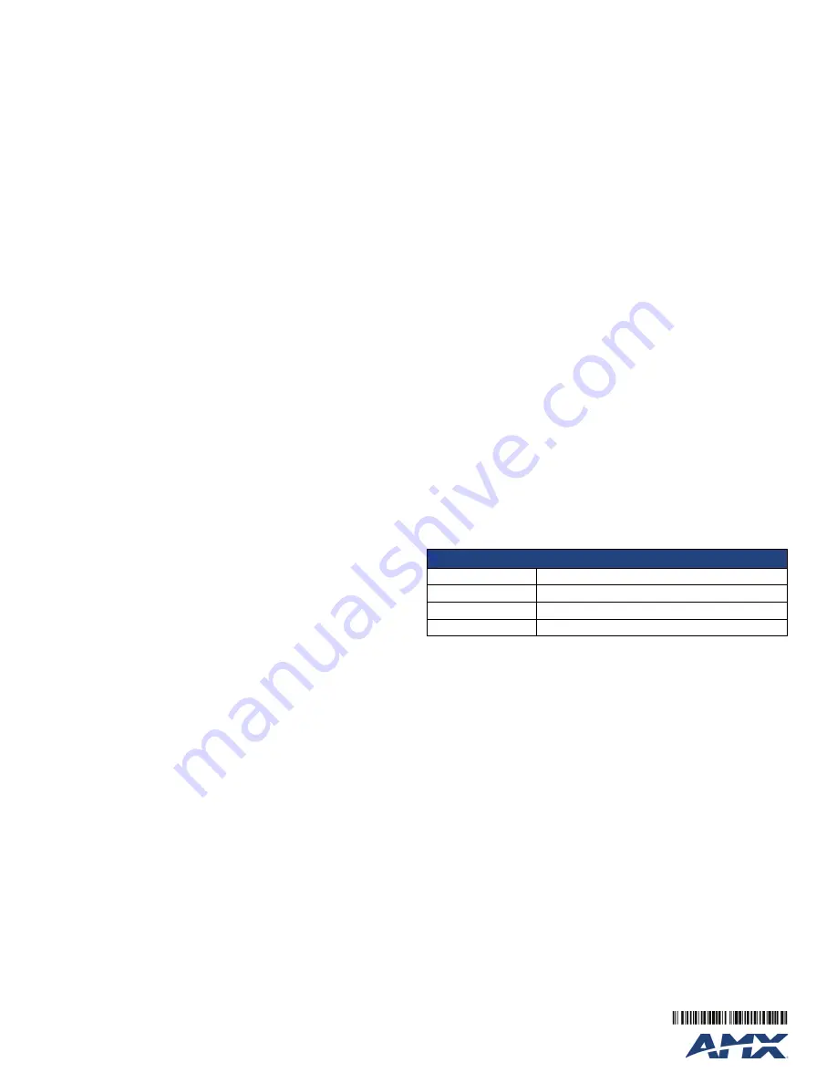
Default settings for the NXA-ENET8PoE
IP Address:
192.168.2.10
Subnet mask:
255.255.255.0
Gateway:
0.0.0.0
Password:
1988