

For full warranty information, refer to the AMX Instruction Manual(s) associated with your Product(s).
6/12
©2012 AMX. All rights reserved. AMX and the AMX logo are registered trademarks of AMX.
AMX reserves the right to alter specifications without notice at any time.
3000 RESEARCH DRIVE, RICHARDSON, TX 75082 • 800.222.0193 • fax 469.624.7153 • technical support 800.932.6993 • www.amx.com
93-2178-63
REV: A
•
Grounding
: Rack-mounted equipment should be properly grounded. Particular atten-
tion should be given to supply connections other than direct connections to the mains
(FIG. 2).
1.
Attach the brackets to the device using the screws provided (FIG. 3):
2.
Mount the device in the rack, using four rack-mounting screws (not provided).
Be sure to secure the lower rack-mounting screws first to prevent the brackets being
bent by the weight of the switch (FIG. 4):
3.
If installing a single switch only, refer to the
Connecting To a Power Source
section.
4.
If installing multiple switches, mount them in the rack, one below the other.
Desktop or Shelf Mounting
1.
Attach the four adhesive feet to the bottom of the first switch.
2.
Set the device on a flat surface near an AC power source, making sure there are at
least two inches of space on all sides for proper air flow.
3.
If installing a single switch only, see
Connecting To a Power Source
below.
4.
If installing multiple switches, attach four adhesive feet to each one. Place each device
squarely on top of the one below.
Connecting To a Power Source
1.
Insert the power cable plug directly into the AC Power Inlet on the rear panel.
2.
Plug the other end of the cable into a grounded, 3-pin, AC power source.
Note
: For international use, you may need to change the AC line cord. You must use a
line cord set that has been approved for the wall socket type in your country.
3.
Check the front-panel LEDs as the device is powered on to be sure the Power LED is
on green. If not, check that the power cable is correctly plugged in.
Connecting Network Devices
The NXA-ENET8-2POE is designed to be connected to 10, 100, or 1000 Mbps network
cards in PCs and servers, as well as to other switches and hubs. It may also be connected to
remote devices using optional 1000BASE-SX, 1000BASELX, 1000BASE-LH, or 100BASE-
FX SFP transceivers.
Twisted-Pair Devices
Each device requires an un-shielded twisted-pair (UTP) cable with RJ-45 connectors at both
ends. Use Category 5, 5e, or 6 cable for 1000BASE-T connections, Category 5 or better for
100BASE-TX connections, and Category 3 or better for 10BASE-T connections.
Power-Over Ethernet Connections
The NXA-ENET8-2POE automatically detects a PoE-compliant device by its authenticated
PoE signature and senses its required load before turning on DC power to the port. This
detection mechanism prevents damage to other network equipment that is not PoE
compliant.
Note
: PoE connections work with all existing Category 3, 4, 5, 5e, or 6 network cabling,
including patch cables and patch-panels, outlets, and other connecting hardware, without
requiring modification.
•
The NXA-ENET8-2POE delivers power to a device using the wire pairs in UTP or STP
cable (RJ-45 pins 1, 2, 3, and 6). The switch can provide up to 34.2 W of power
continuously on each of the eight RJ-45 ports. If a device tries to draw more than
34.2 W from a port, an overload condition occurs and the port disables the power.
•
The NXA-ENET8-2POE controls the power and data on a port independently. Power
can be requested from a device that already has a data link to the switch.
•
Also, the NXA-ENET8-2POE can supply power to a device even if the port’s data
connection has been disabled. The power on a port is continuously monitored by the
NXA-ENET8-2POE and it will be turned off as soon as a device connection is
removed.
Cabling Guidelines
The RJ-45 ports on the NXA-ENET8-2POE supports automatic MDI/MDI-X pinout
configuration, so you can use standard straight-through twisted-pair cables to connect to any
other network device (PCs, servers, switches, routers, or hubs). See the
NXA-ENET8-2POE
Operation/Reference Guide
for further information on cabling.
Note
: Do not plug a phone jack connector into an RJ-45 port. This will damage the switch.
Use only twisted-pair cables with RJ-45 connectors that conform to FCC standards.
Connecting to PCs, Servers, Hubs and Switches
1.
Connect one end of a twisted-pair cable segment to the NXA-ENET8-2POE’s RJ-45
connector.
2.
If the device is a network card and the switches are in the wiring closet, connect the
other end of the cable segment to a modular wall outlet that is connected to the wiring
closet.
Otherwise, connect the other end of the cable segment directly to an available port on
the switch.
Make sure each twisted pair cable does not exceed 100 meters (328 ft) in length.
3.
As each connection is made, the Link LED (on the switch) corresponding to each port
will turn on (green or amber) to indicate that the connection is valid.
Cables and Pinouts
Twisted-Pair Cable Assignments
For 10/100BASE-TX connections, a twisted-pair cable must have two pairs of wires. For
1000BASE-T connections the twisted-pair cable must have four pairs of wires. Each wire pair
is identified by two different colors.
For example, one wire might be green and the other, green with white stripes. Also, an RJ-45
connector must be attached to both ends of the cable. FIG. 5 illustrates how the pins on the
RJ-45 connector are numbered.
Note
: Be sure to hold the connectors in the same orientation when attaching the wires to the
pins.
Auto-Negotiation / MDI-X Support
Auto-negotiation MDI/MDIX means that every port on the switch will automatically detect the
Ethernet cable type being used (straight-through or crossover) and adjust to make a link over
that cable. The NXA-ENET8-2POE supports MDI-X on all ports. Therefore either cable type
can be used.
Note
: Follow TIA-568B straight-through cabling standards.
10/100BASE-TX Pin Assignments
Use un-shielded twisted-pair (UTP) or shielded twisted-pair (STP) cable for RJ-45
connections: 100-ohm Category 3 or better cable for 10 Mbps connections.
Note:
Be sure that the length of any twisted-pair connection does not exceed 100 meters
(328 feet).
Using the Web Console
The NXA-ENET8-2POE provides an embedded HTTP web agent. Using a web browser you
can configure the switch and view statistics to monitor network activity. The Web Console
can be accessed by any computer on the network using a standard web browser (Internet
Explorer 5.0, Netscape 6.2, Mozilla Firefox 2.0.0.0, or more recent versions).
Default Login Information
Default IP Address
The default IP Address for the NXA-ENET8-2POE is:
192.168.1.10
.
Default User Name and Password
To access the Web Console interface you must first enter a user name and password. The
administrator has Read/Write access to all configuration parameters and statistics.
The default
User Name
and
Password
for the administrator is “
admin
.”
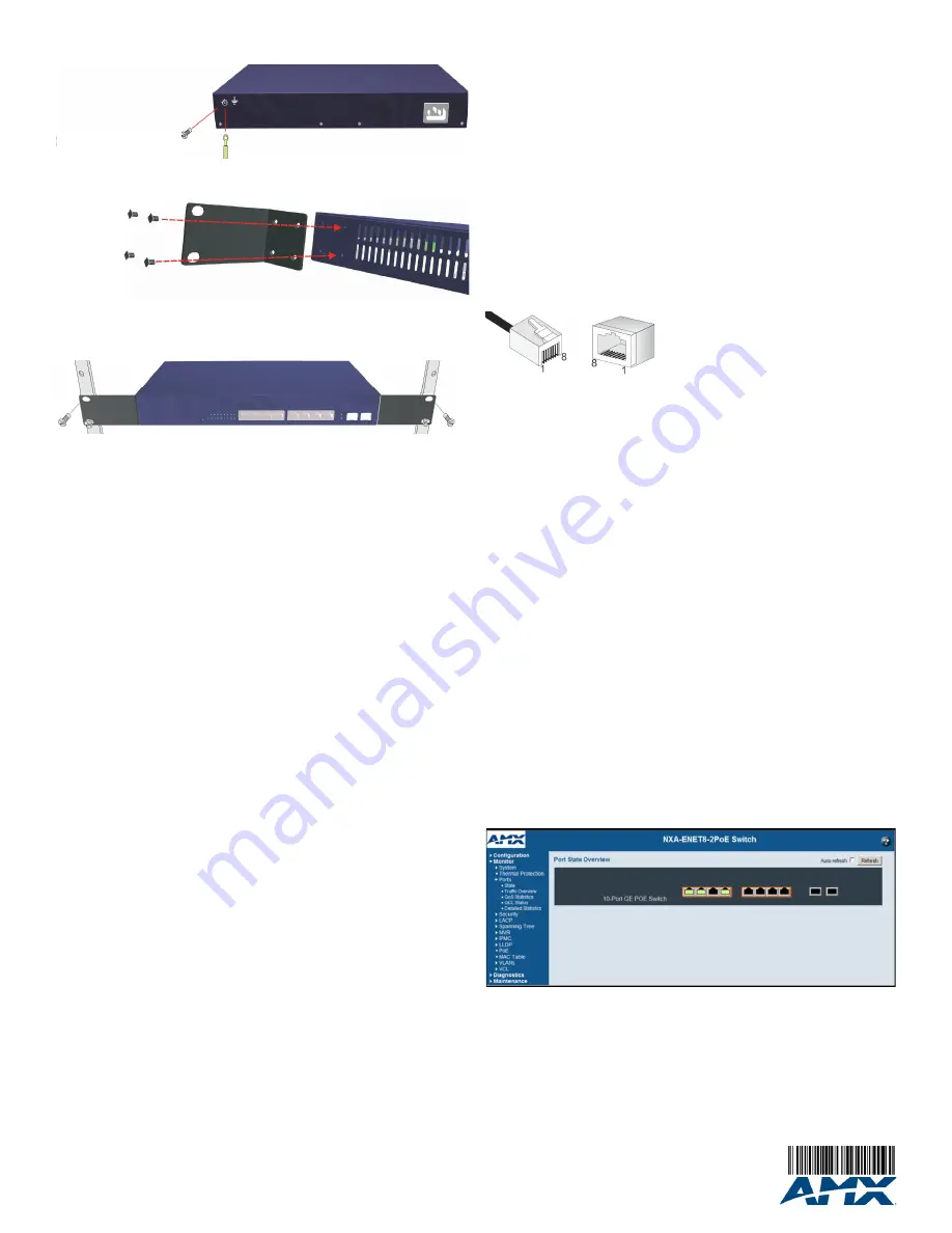
Home Page
When your web browser connects with the switch’s web agent, the home page is displayed
as shown below. The home page displays the Main Menu on the left side of the screen and
an image of the front panel on the right side. The Main Menu links are used to navigate to
other menus, and display configuration parameters and statistics.
Refer to the
NXA-ENET8-2POE Operation/Reference Guide
for instructions on using the
Web Console to configure the switch. The
Operation/Reference Guide
also provides detailed
and instructions on using the Web Console to monitor the switch as well as perform
diagnostics and maintenance.
Additional Documentation
Refer to the
NXA-ENET8-2POE Operation/Reference Guide
for additional installation and
cabling details (including fiber optic cable), as well as detailed Compliance and Safety
information.
FIG. 2
Grounding
FIG. 3
Attaching the Brackets
FIG. 4
Installing the NXA-ENET8-2POE in a Rack
Terminate the wire in an earthed grounding point
Attach an insulated grounding
wire with a metal screw, to the
marked Grounding Point
FIG. 5
RJ-45 Connector
FIG. 6
Web Console - Home Page