

AMX Corporation reserves the right to alter specifications without notice at any time.
For full warranty information, refer to the AMX Instruction Manual(s) associated with your Product(s).
060-004-2725 02/04 ©2004
AMX Corporation. All rights reserved. The AMX logo is a trademark of AMX Corporation. AMX reserves the right to alter specifications without notice at any time.
3000 RESEARCH DRIVE, RICHARDSON, TX 75082 • 800.222.0193 • fax 469.624.7153 • technical support 800.932.6993 • www.amx.com
93-2062
REV: C
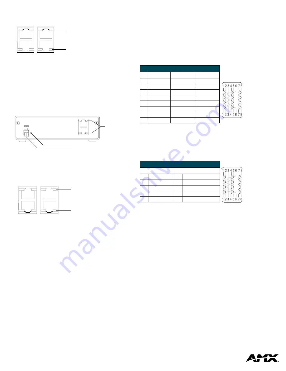
Rear Panel LEDs
FIG. 5 shows the layout of the ICSHub LEDs.
NXC-HE ICSHub Expander Card
The NXC-HE ICSHub Expander Card can be used as an ICS hub cable
extender where runs between ICS hubs are over 1,000 feet (304.8 m). The
NXC-HE Card can also be used in place of a Master card in a NXI (NetLinx
Integrated Controller) or NXF (CardFrame) to be used as slave devices. FIG. 6
shows its rear panel components.
Rear Panel LEDs
FIG. 7 shows the layout of the ICSHub LEDs.
Installation and Wiring
Mounting the Modules into an equipment rack
To install the Modules into an equipment rack, you'll need an optional AC-RK
Kit:
1.
Remove the front faceplate from the Module to expose the mounting
holes.
2.
Mount the module on the AC-RK bracket.
3.
Place the AC-RK bracket (with the module) in the equipment rack and
secure the bracket to the rack.
4.
Replace the front panel to the Module, and attach the magnetic, translu-
cent faceplate (if necessary).
Preparing/connecting captive wires
1.
Strip 0.25 inch of wire insulation off all wires.
2.
Insert each wire into the appropriate opening on the connector according
to the wiring diagrams and connector types described in this section.
•
Do not tighten the screws excessively; doing so may strip the threads and
damage the connector.
ICSNet RJ-45 Connections/Wiring
The following table shows the pinouts, signals, and pairing information to use
for ICSNet RJ-45 connections. The ICSNet connections provide power and
data to ICSNet devices. Each port provides up to 500 mA of current.
ICSHub RJ-45 Connections/Wiring
Use CAT5 cables for all ICSHub connections.
Do not
connect the last hub in a daisy-chain configuration into the first hub.
The following table shows the pinouts and signals for ICSHub RJ-45
connections.
FIG. 5
Layout of the ICSHub IN/OUT LEDs
FIG. 6
NXC-HE Card/Module (shown mounted in NXM-MHS Module - rear view)
FIG. 7
Layout of the ICSHub IN/OUT LEDs.
ICSNet
OUT
ICSHub
IN
ICSHub IN LED (yellow):
lights to indicate data input
activity on this port
ICSHub OUT LED (yellow):
lights to indicate data transfer
activity on this port
NXC-HE
ICSHub Expander
12VDC
PWR
ICSHub
OUT
IN
ICSHub
IN/OUT
connectors
and LEDs
Power Supply indicator LED (green)
12 VDC Power Supply connector
ICSNet
OUT
ICSHub
IN
ICSHub OUT LED (yellow):
lights to indicate data transfer
activity on this port
ICSHub IN LED (yellow):
lights to indicate data input
activity on this port
ICSNet RJ-45 Pinouts/Signals
Pin
Signal
Connections
Pairing
1
TX +
1 --------- 1
1 --------- 2
2
TX -
2 --------- 2
3
Mic -
3 --------- 3
3 --------- 6
4
GND
4 --------- 4
5
12 VDC
5 --------- 5
4 --------- 5
6
Mic +
6 --------- 6
7
RX +
7 --------- 7
7 --------- 8
8
RX -
8 --------- 8
ISCSHub Pinouts and Signals
IN Port
OUT Port
Pin
Signal
Pin
Signal
1
TX -
1
RX +
2
TX +
2
RX -
7
RX -
7
TX +
8
RX +
8
TX -
RJ-45 plug
RJ-45 plug
RJ-45 plug
RJ-45 plug


