

For full warranty information, refer to the AMX Instruction Manual(s) associated with your Product(s).
6/14
©2014 AMX. All rights reserved. AMX and the AMX logo are registered trademarks of AMX.
AMX reserves the right to alter specifications without notice at any time.
3000 RESEARCH DRIVE, RICHARDSON, TX 75082 • 800.222.0193 • fax 469.624.7153 • technical support 800.932.6993 • www.amx.com
93-5968-42
REV: B
10. Insert the four temporary mounting posts of the panel into the openings on the Backbox
and slide the panel onto the Backbox. This will temporarily hold the panel during the rest
of the installation (FIG. 5).
WARNING: When installing the panel, do NOT press on or near the center of the panel.
Too much stress at the center may damage the touch screen surface. When installing the
panel, pressure should be applied toward the ends of the panel ONLY.
11. Use the six provided screws, three at each end, to secure the touch panel to the Backbox
(FIG. 5). Use only the provided screws, as other screws may damage the touch panel.
12. Snap the side covers onto each end of the touch panel.
13. Reconnect the terminal Ethernet and USB to their respective locations on either the
Ethernet port or NetLinx Master.
Panel Connectors and Wiring
Connectors are located on the underside of the MXD-1901-PAN. The Micro-USB port is used
for camera video output. A second, limited access USB port is accessible on the back side of
this cover.
Wiring Guidelines
The MXD-1901-PAN uses a 12 VDC-compliant power supply to provide power to the panel
via the 2-pin 3.5 mm captive wire PWR connector. Use the previously provided power
requirement information to determine the power draw. The incoming PWR and GND wires
from the power supply must be connected to the corresponding locations within the PWR
connector.
Note: Apply power to the panel only after installation is complete.
Note: Connecting power to the MXD-1901-PAN should be done using the included 2-pin
3.5mm captive wire connector included with the device. This connector uses retaining
screws (instead of the pins on each side of standard captive wire connectors); using
excessive force to insert a standard captive wire connector may damage the device.
Wiring a Power Connection
To use the 2-pin 3.5 mm captive wire connector with a 12 VDC-compliant power supply, the
incoming PWR and GND wires from the external source must be connected to their
corresponding locations on the connector (FIG. 6).
The connector uses locking screws to insure a connection to the device, so make sure to
insert and tighten the screws before applying power.
1. Insert the PWR and GND wires into the terminal end of the 2-pin 3.5 mm captive wire
connector cable.
Match the wiring locations of the +/- on both the power supply and the
terminal connector.
2. Tighten the clamp to secure the two wires.
Do not tighten the screws excessively; doing
so may strip the threads and damage the connector.
3. Verify the connection of the 2-pin 3.5 mm captive wire connector to the external 12 VDC-
compliant power supply and apply power.
Powering On/Off X Series G5 Panels
G5 touch panels may be powered on by touching and holding the
Sleep
button. To power off
the panel, press and hold the Sleep button, and select
Power Off
on the on-screen menu.
Configuration and Programming
G5 touch panels are equipped with a
Settings
menu that provides the ability to configure
various features on the panels. To access the
Settings
menu, press and hold the Sleep
button, and select
Settings
.
Note: Information on the Settings menu, panel configuration, and programming is provided in
the
Modero X Series G5 Programming Guide
, available at www.amx.com.
Setting the Panel’s Device Number and Device Name
1. In the Settings menu, select
NetLinx
. This opens a password keypad.
2. Enter the panel password into the keypad (the default is
1988
) and select
OK
to access
the
NetLinx
page.
3. Press
Device Number
to open the NetLinx editing window.
4. Enter a unique Device Number assignment for the panel and press
OK
.
5. Enter a unique Device Name assignment for the panel and press
OK
.
Configuring the Panel’s IP Address
These steps configure the panel to communicate with a network; it is still necessary to
connect to the NetLinx Master (see
Connecting to a NetLinx Master
below).
Network Communication via DHCP
1. In the
Ethernet
page, press
DHCP/Static
field to open the
DHCP/Static
window. Note
that
DHCP
is the default setting.
2. Select
Host Name
, enter the new host name
3. Press
OK
to save changes.
Network Communication via Static Address
1. In the
Ethernet
page, press
DHCP/Static
to open the
DHCP/Static
window.
2. Select
Static
to open the
Static IP
window.
3. Press any field to open a keypad or keyboard (depending on the field), and enter the
appropriate network address information.
4. Press
OK
to save your changes and return to the
Ethernet
page.
Connecting to a NetLinx Master
To establish the type of connection to make between the panel and the NetLinx Master:
1. In the
NetLinx
page, press
Mode
to choose the connection mode (
URL
,
Listen
or
Auto
):
2. If password security is enabled on the target Master, enter the Username and
Password:
a. Select
Username
to open the
NetLinx
window.
b. Enter the
Username
and
Password
required by the Master.
c.
Press
OK
to save changes and return to the
NetLinx
page.
Related Software and Additional Documentation (at www.amx.com
•
Programming the Modero X Series G5 touch panels requires the use of the latest
versions of NetLinx Studio and TPDesign5, both available to download at
www.amx.com. Refer to the NetLinx Studio and TPDesign5 online help for information.
•
For additional information on the MXD-1901-PAN, refer to the
X-Series-G5 Touch
Panels MXD/T-1901-PAN & MXD/T-2001-PAN Instruction Manual.
•
For detailed information on the Settings menu as well programming information and
instructions on upgrading firmware, refer to the
Modero X Series G5 Programming
Guide
.
FIG. 4
MXD-1901-PAN Backbox installation (Landscape)
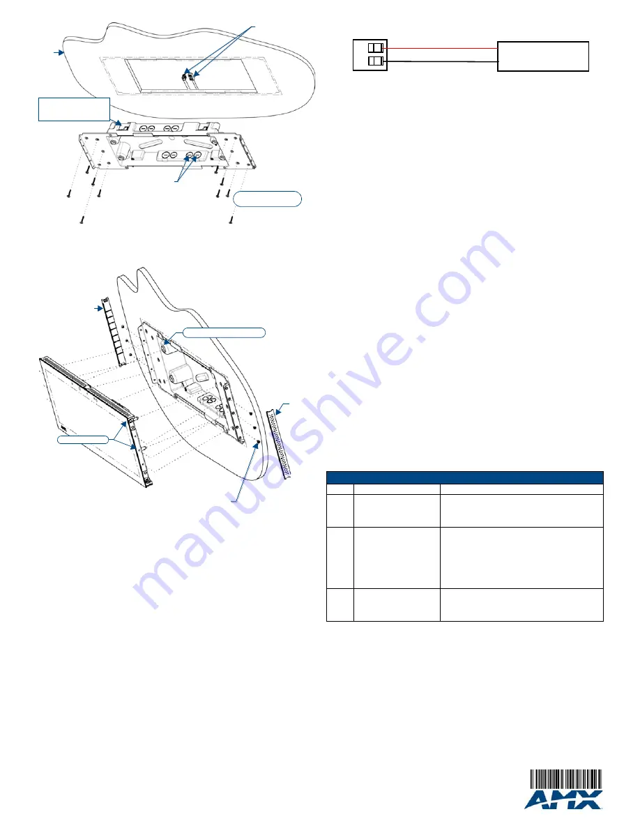
FIG. 5
MXD-1901-PAN installation (Landscape)
Mounting screws
placement (optional)
Wall
Cables routed to
wall opening
8X Knock Outs
Remove For Cable
Routing As Needed
4X Installation Clamp
For Wall Thickness
.37 [12.01] to .98 [25.01]
Side cover
4X Mounting post openings
4X Mounting posts
6X 4-40 X 1/4" LONG FLAT HEAD
TORQUE TO 5±.2 IN LBS
Side
cover
FIG. 6
NetLinx power connector wiring diagram
Connection Modes
Mode
Description
Procedures
URL
The device connects to the
target Master’s IP address
via a TCP connection.
1) Select
URL
in the
Mode
menu.
2) Enter the
Master IP/URL
,
Master Port Number
, and
Username
/
Password
(if required by the Master).
3) Press
OK
to save changes.
Listen
This mode allows the panel
to “listen” for the Master’s
communication signals.
Note that in this mode, the
System Number
and
Master
IP/URL
fields are read-only.
1) Select
Listen
in the
Mode
menu.
2) Confirm the panel’s IP address is on the Master’s URL
list (via NetLinx Studio).
3) Press
OK
to save changes.
Note: The Host Name (set on the
Ethernet
page), can be
used to locate the panel on the Master (particularly
useful for DHCP connections where the IP address can
change).
Auto
Use this mode when both the
panel and the NetLinx Mas-
ter are on the same Subnet.
1) Select
Auto
in the
Mode
menu.
2) Enter the System Number and Username and
Password (if applicable).
3) Press
OK
to save changes.
PWR +
GND -
To the Touch Panel
Power Supply


