background image

MVP-WDS Wall Docking Station & CB-MVPWDS Rough-In Box

8

MVP-WDS Wall Docking Station for MVP Panels

Installing the MVP-WDS in a CB-MVPWDS Rough-In Box


The rough-in box must be mounted prior to continuing this section. Refer to the 

Installing the 

CB-MVPWDS Rough-In Box

section on page 4 for detailed pre-wall installation instructions.


The faceplate must be removed prior to any surface installation (see the 

Removing the MVP-

WDS Faceplate

section on page 5).


Verify that the USB and power cables have been threaded through the knockouts on the right 
of the rough-in box. Leave enough slack in the wiring to accommodate re-positioning of the 
panel.

1.

Connect the 2-pin power connector and USB cables to the WDS. The WDS must be installed with 
these attached. The USB connectors can be from either a USB extension cable, or a wireless USB 
RF transmitter.

2.

Insert the WDS into the rough-in box, so that the Mounting Tabs on the WDS lie flush against the 
rough-in box (FIG. 9).  

Verify that the terminal end of the power cable is not connected to a power source 
before plugging in the 2-pin power connector.
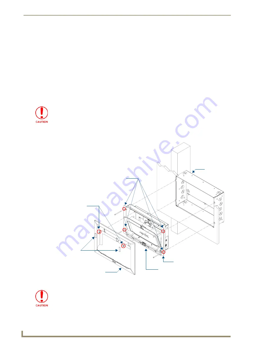
FIG. 9  

MVP-WDS installation configuration within a CB-MVPWDS Rough-In Box

MVP-WDS (Main unit) 

#6-32 Mounting Screws 

(4 - not included) 

Faceplate

Mounting Tab

Die Cut Foam


CB-MVPWDS
Rough-In Box

covers (2)

#6-32 Faceplate

Security Screws (2)

See CAUTION after Step 3 below


secure the WDS to the Rough-In Box

The MVP-WDS must be mounted on a flat surface.

Summary of Contents for MVP-WDS

Page 1: ...Installation Guide Touch Panels Accessories MVP WDS Wall Docking Station for MVP 7500 8400 Modero ViewPoint Wireless Touch Panels Last Revised 12 15 2008 ...

Page 2: ... or after the RMA is cancelled will be refused AMX is not responsible for products returned without a valid RMA number AMX is not liable for any damages caused by its products or for the failure of its products to perform This includes any lost profits lost savings incidental damages or consequential damages AMX is not liable for any claim made by a third party or by an AMX Dealer for a third part...

Page 3: ...owever there is no guarantee that interference will not occur in a particular installation If this equipment does cause harmful interference to radio or television reception which can be determined by turning the equipment off and on the user is encouraged to try to correct the interference by one or more of the following measures Reorient or relocate the receiving antenna Increase the separation ...

Page 4: ......

Page 5: ...or Power 14 Connecting and Using USB Input Devices on the Stations 15 Interface Connector Pins and Functions 15 Securing an MVP Panel to an MVP WDS 16 Removing an MVP Panel from an MVP WDS 17 Unsecured MVP removal from an MVP WDS 17 Secured MVP removal from an MVP WDS 17 Undock USER String 18 Installing and Charging Batteries in the Docking Stations 18 Installing MVP BP Batteries Into the MVP WDS ...

Page 6: ...ii MVP WDS Wall Docking Station for MVP Panels Table of Contents ...

Page 7: ...ing the Web via the G4 Computer Control application Another key feature of the MVP WDS is that it can be mounted into either a solid surface using surface screws or into an optional CB MVPWDS rough in box for pre wall installation These two installation options allow the MVP to be mounted into virtually any surface environment Refer to the Installation section on page 4 for more information FIG 1 ...

Page 8: ...male that connect to the underside MVP connector strip This connection provides both communication and power between the MVP and the MVP WDS Support Cradle This retractable mechanism supports a resting MVP panel and allows a user to either insert or remove a connected MVP panel LEDs Two blue LEDs indicate either Left LED monitors the battery status within either the MVP WDS or MVP Right LED monito...

Page 9: ...zel Faceplate 60 5965 20SL One Silver Cradle Pivot 60 5965 21SL One Silver Battery Cover 60 5965 22SL One securing rare earth magnet 63 5965 02 One securing magnet cup 63 5965 03 One 4 20 Magnet Securing screw 80 0193 01 Two plastic Die Cut Foam covers 60 5965 47 FIG 2 Connector layout on the side of the MVP WDS LED Pattern Indicators for the MVP WDS LED Left Battery Status Right Comm Status WDS o...

Page 10: ...s so that you can make any necessary cutout adjustments The CB MVPWDS can be installed with the removable access panel positioned either on top or bottom The access panel provides convenient access to in wall wiring and must be re installed prior to mounting the MVP WDS 1 Place the left side of the rough in box on a stud making sure that five Stud Fastening Holes and removable Access Panel are ori...

Page 11: ...e faceplate screws only after the installation is complete and the support cradle is retracted 1 Place the MVP WDS face up on a flat level surface 2 Connect the mini Phoenix connector from a compatible 12V power supply to the PWR connector on the side panel see FIG 4 to apply power 3 Open the Battery Compartment and press the Cradle Activation pushbutton recessed white button located near the pins...

Page 12: ... upwards and pull it up and over the Security Latch 7 Grab the bottom rim of the faceplate and push it up towards the support cradle then pull it out sliding the four faceplate connectors out of the latches along the bottom of the WDS FIG 7 FIG 5 Cradle activation pushbutton location and cradle angling FIG 6 Faceplate screw removal Battery Compartment Cover Battery Compartment Latch Cradle MVP Sup...

Page 13: ... rim of the faceplate and carefully slide it over the cradle at an angle until the faceplate is completely removed from the WDS FIG 8 Once the faceplate has been removed you can continue the installation of the WDS FIG 7 Faceplate securing latch and connector locations FIG 8 Faceplate removal from MVP WDS Faceplate Securing Latches Faceplate Connectors Faceplate Faceplate securing latches ...

Page 14: ...re positioning of the panel 1 Connect the 2 pin power connector and USB cables to the WDS The WDS must be installed with these attached The USB connectors can be from either a USB extension cable or a wireless USB RF transmitter 2 Insert the WDS into the rough in box so that the Mounting Tabs on the WDS lie flush against the rough in box FIG 9 Verify that the terminal end of the power cable is not...

Page 15: ... clip The faceplate must be removed prior to any surface installation see the Removing the MVP WDS Faceplate section on page 5 The outer frame Mounting Tabs must be flush against the mounting surface 1 Cut out the surface for the WDS using the dimensions shown in installation diagram SP 5965 01 reproduced in FIG 11 on page 10 It is recommended that you cutout the surface slightly smaller than what...

Page 16: ...lips into the four oval notch locations along both sides of the main unit FIG 12 5 Carefully insert the main unit with expansion clips into the cutout so that the Mounting Tabs on the MVP WDS lie flush against the wall Verify that the terminal end of the power cable is not connected to a power source before plugging in the 2 pin power connector FIG 11 MVP WDS Wall Mount cutout dimensions using exp...

Page 17: ...Refer to SP 5965 01 for detailed installation dimensions reproduced in FIG 13 It is recommended that you cutout the surface slightly smaller than what is outlined in the installation drawings so that you can make any necessary cutout adjustments The outer frame Mounting Tabs must be installed so that they are flush against the mounting surface 1 Cut out the surface for the MVP WDS docking station ...

Page 18: ...lly installing the WDS Refer to the LED Indicators table on page 3 for blink pattern information 5 Disconnect the terminal end of the power cable from the connected power supply 6 Carefully insert the main unit into the cutout until the Mounting Tabs on the MVP WDS lie flush against the wall FIG 14 FIG 13 MVP WDS Wall Mount cutout dimensions using solid surface screws R 13 3 2MM MAX RADIUS IN 4 CO...

Page 19: ...the MVP WDS 4 Slide the Faceplate over the angled Support Cradle toward the Security Release pushbutton s circuit board on the MVP WDS FIG 9 5 Gently press the faceplate down and under the Security Latch until it rests against the Mounting Tabs of the MVP WDS main unit Be sure to snap the Faceplate Connectors back into their respective Latches located along the bottom rim of the faceplate see FIG ...

Page 20: ...ts battery compartments 1 Connect the terminal end of the power supply to the rear PWR connector on the WDS 2 Provide power to the MVP WDS by connecting the AC power cord to an external power source Initially both blue LEDs illuminate and remain dim indicating that the power is being supplied to the MVP WDS Using the 3 5mm mini Phoenix Connector for Power To use the 2 pin 3 5 mm mini Phoenix conne...

Page 21: ...the mouse cursor position sent by the external USB mouse If a USB keyboard has been connected only on screen keyboards and keypads will reflect any external keystrokes sent from the external USB keyboard To be detected by the docking station USB input devices keyboard mouse must be plugged into the docking station before it is powered up The docking station will not detect USB input devices until ...

Page 22: ...ow one second to activate the electromagnet When the MVP is properly docked the following message is displayed on the panel FIG 18 Proper docking and communication can be verified via the on screen system message or the illuminated Docking Status button on the Protect Setup page or the right LED on the docking station FIG 16 MVP TDS Connector Pin locations and Pinout function FIG 17 Installing an ...

Page 23: ...ort cradle 3 Allow the MVP WDS one second to retract the Support Cradle Secured MVP removal from an MVP WDS 1 Press and hold the security release pushbutton until the on screen keypad appears on the MVP 2 Enter the security release password 3 Press Done when finished Allow the MVP WDS one second to process the release request and turn off the electromagnet 4 Angle the MVP forward 5 Lift the panel ...

Page 24: ...efer to the MVP 7500 8400 Operation Reference Guide available online at www amx com for more information on setting up a User Access username and password Installing MVP BP Batteries Into the MVP WDS The MVP WDS connects directly to a PSN4 4 power supply and provides both power and communication to docked MVP panel The MVP WDS can charge batteries in its own battery compartments as well as those w...

Page 25: ...page 4 2 Carefully remove the previously adhered Die Cut Foam covers from the WDS backplate FIG 19 These must be removed to gain access to the two 6 32 Faceplate Security Screws New covers are included with the MVP WDS SK Conversion Kit 3 Place the back of the MVP WDS Docking Station on a flat level surface 4 Connect the 3 5 mm mini Phoenix connector from an active power supply to the side PWR con...

Page 26: ... with both hands and in one motion pull the top rim of the faceplate directly towards you and then over the Security Latch to allow it to be removed from the main unit 12 Grab the bottom rim of the faceplate and place your thumbs just below either side of the Security Release Pushbutton 13 In one single motion use your thumbs to push the bottom rim towards the cradle and then pull it upwards to sl...

Page 27: ...e unit just above the USB connectors FIG 22 and set them aside 2 Insert the screwdriver into the large hole on the side of the existing black WDS housing FIG 22 3 Position the unit to allow a clear view through the gap between the cradle and the rim of the metallic WDS housing FIG 23 This view allows you to orient the alignment between the tip of the screwdriver and the screw holding the support c...

Page 28: ... Interface Connector pin circuit board and use the screwdriver to remove this board from the combo unit by unscrewing the two screws A in FIG 25 FIG 23 Separating the support cradle from its movement mechanism FIG 24 Sliding out the battery cover support cradle combo Support Cradle Pivot movement mechanism Long Magnetic Phillips head screwdrivers Attachment screw Gap opening MVP Support Cradle Sec...

Page 29: ...arefully secure this board to the backside of the unit using the three securing screws 3 Rotate the pivot unit back over to expose the installation location for the MVP Interface Connector pin circuit board A in FIG 25 and use a grounded Phillips head screwdriver to secure this remaining board to the silver pivot unit by screwing in the two securing screws 4 Install the silver Battery Cover to the...

Page 30: ...it by using a grounded flat head Phillips screwdriver to screw in the single 4 20 Magnet Securing screw 80 0193 01 through the cup 12 Place the small circular rare earth magnet 68 5965 02 into the secured magnetic cup The charge on the magnet allows it to stay in place and remain flush against the magnetic cup Installing the new silver faceplate 1 Turn the pre existing black faceplate over to expo...

Page 31: ...he MVP WDS main unit Be sure to snap the Faceplate Connectors into their respective Latches located along the bottom rim of the faceplate see FIG 21 on page 21 Verify that the two faceplate security screw holes on both the Faceplate and the main MVP WDS unit are properly aligned 7 Insert and secure the two 6 32 Faceplate Security Screws into the top rim of the Faceplate using a screwdriver 8 Apply...

Page 32: ...MVP WDS Wall Docking Station CB MVPWDS Rough In Box 26 MVP WDS Wall Docking Station for MVP Panels ...

Page 33: ... entered within the Send to NetLinx Device transfer dialog in Studio Step 1 Prepare the Docking Station for firmware transfer via USB Before beginning with this section Verify the MVP is securely attached to the docking station and communicating properly Verify that the panel is communicating from the mini USB port to the Virtual NetLinx Master VNM 1 Configure the NetLinx Master for IP communicati...

Page 34: ...the desired Kit file link and after you ve accepted the Licensing Agreement verify you have downloaded the Docking Station Kit file to a known location 7 Select Tools Firmware Transfers Send to NetLinx Device from the Main menu to open the Send to NetLinx Device dialog FIG 3 Verify the panel s System and Device number values match those values listed within the System folder in the OnLine Tree tab...

Page 35: ...ter and populates the System list with devices on your particular system 15 After the panel powers up press and hold the two lower buttons on both sides of the display for 3 seconds to continue with the setup process and proceed to the Setup page 16 Press the Batteries button located on the lower left to open the Batteries page and confirm the new firmware does not read 0 00 FIG 3 Send to NetLinx ...

Page 36: ...upgrades can be done over wireless Ethernet it is recommended that firmware KIT files be transferred over a direct USB connection and only when the panel is connected to a power supply If battery power or wireless connection fails during a firmware upgrade the panel flash file system may become corrupted ...

Page 37: ...Upgrading the Docking Station Firmware 31 MVP WDS Wall Docking Station for MVP Panels ...

Page 38: ...ed trademarks of AMX AMX reserves the right to alter specifications without notice at any time It s Your World Take Control 3000 RESEARCH DRIVE RICHARDSON TX 75082 USA 800 222 0193 469 624 8000 469 624 7153 fax 800 932 6993 technical support www amx com 93 5965 13 REV E ...

Reviews: