

For full warranty information, refer to the AMX Instruction Manual(s) associated with your Product(s).
12/07
©2007 AMX. All rights reserved. AMX and the AMX logo are registered trademarks of AMX.
AMX reserves the right to alter specifications without notice at any time.
3000 RESEARCH DRIVE, RICHARDSON, TX 75082 • 800.222.0193 • fax 469.624.7153 • technical support 800.932.6993 • www.amx.com
93-5965-10
REV F
Connections and Wiring
The
PS4.4
can be used to indirectly supply power to the MVP by routing
incoming power through the connector pins and charge any batteries inserted
within the MVP-TDS’ rear charging compartments (FIG. 3).
• Once the MVP is connected to this MVP Docking Station,
charging is first applied to any MVP-BP batteries found within the panels’
rear battery compartment and then to any batteries inserted within the
MVP-TDS’s battery compartments.
Powering the MVP-TDS
The MVP-TDS uses a PS4.4 power supply (not included) to provide direct
power for the MVP panel, while charging internal batteries.
Note:
Once MVP batteries are fully charged, the MVP-TDS begins charging
MVP-BP batteries inserted within its rear battery compartments.
1.
Connect the terminal end of the PS4.4 power supply to the rear PWR
connector on the TDS.
2.
Provide power to the MVP-TDS by connecting the PS4.4 cord to an exter-
nal power source.
Note:
Initially, both blue LEDs (FIG. 4) illuminate and remain dim (indicating
that the power is being supplied to the MVP-TDS).
Reading MVP-TDS LED Indicators
FIG. 4 shows the front LED locations on the MVP-TDS Table Top Docking
Station.
The two LED indicators (beneath the front security release pushbutton) (FIG. 4)
indicate both the battery and communication status as follows:
Mounting an MVP to the MVP-TDS
1.
Place the MVP-TDS Table Top Docking Station on a flat and level
surface.
2.
Provide power to the MVP-TDS (refer to the previous
Powering the MVP-
TDS
section for more details).
3.
Carefully grasp both sides of the MVP panel and use the MVP-TDS align-
ment guide pins to position the MVP panel atop the MVP
Support Cradle (with a downward motion) (FIG. 5).
4.
Verify that the alignment guide pins (male) are correctly inserted into the
MVP alignment guide insertion holes (located just below the AMX logo
and along the lower edge of the MVP). Without proper
connection, the MVP will not be able to communicate with or receive
power from the MVP-TDS.
5.
Once a proper alignment is verified, gently angle back the MVP on the
cradle until the rear of the panel makes contact with the
electromagnet. Allow one second to activate the electromagnet.
Note
: If the MVP is docked properly and communicating, the right LED will
remain brightly illuminated on the MVP-TDS. Refer to the LED Pattern Indicator
table for more information. If the MVP is not properly docked, the right LED will
remain Off or Dim.
CAUTION
: Be very careful when testing the proper connection of the MVP to
the MVP-TDS. If the panel is not securely attached, the electromagnet will not
be activated, and the panel could fall off and become damaged.
Removing the MVP panel from an unsecured MVP-TDS
1.
Press and hold the front panel security release pushbutton (FIG. 4). Allow
one second for the electromagnet to turn-off.
2.
Grasp the MVP panel from both sides and gently angle it forward.
3.
Carefully lift the panel from the MVP-TDS cradle in an upward
direction to remove the guide pins from the insertion holes.
Removing the MVP panel from a secured MVP-TDS
1.
Press and hold the front panel security release pushbutton (FIG. 4) until
an on-screen security keypad appears within the MVP LCD.
2.
Enter the security release password into the on-screen keypad.
This password has been previously entered by the installer or
administrator through the Passwords page.
3.
Press
Done
when finished and allow the TDS one second to process the
release request.
Note
: Once the release command has been processed and accepted, the
MVP-TDS turns-off the electromagnet.
4.
Grasp the MVP panel from both sides and gently angle it forward.
5.
Carefully remove the panel from the MVP-TDS cradle in an upward direc-
tion to remove the guide pins from the insertion holes.
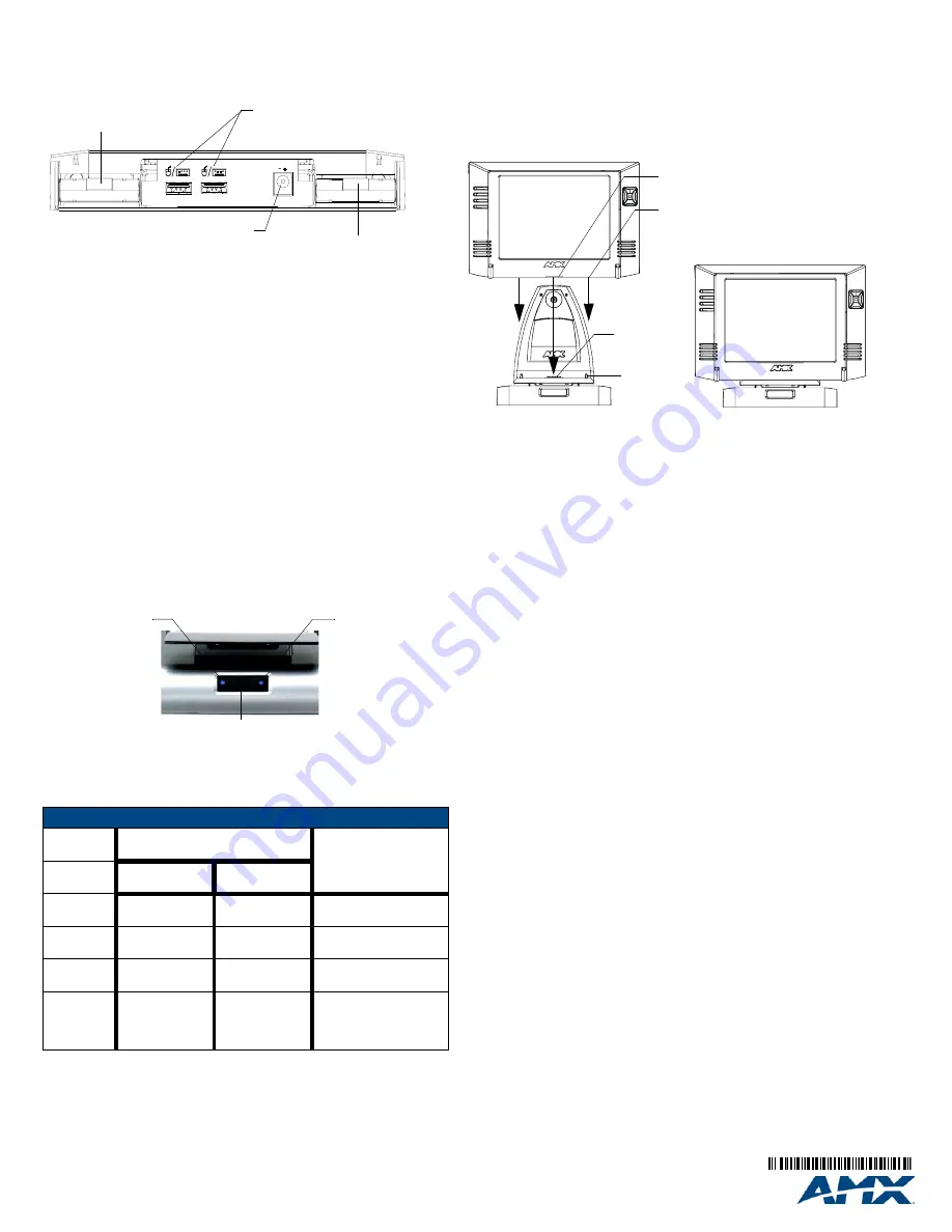
FIG. 3
MVP-TDS rear connectors and battery compartments
FIG. 4
MVP-TDS front panel LED locations
LED Pattern Indicators
LED
Illumination
Left LED - Battery Status
Right LED -
Comm. Status
Docking Station
only
MVP in Cradle
Solid
Bright
TDS batteries are
fully charged
MVP batteries are
fully charged
MVP panel is docked and
communicating
Flashing
Bright (Slow)
TDS batteries are
charging
MVP batteries are
charging
N/A
Flashing
Bright (Fast)
N/A
N/A
MVP panel is docked
but not communicating
Solid Dim
TDS receiving
power but
contains no
batteries in cradle
No batteries
within the MVP
MVP panel is
NOT
docked
and
NOT
communicating
MOUSE
KEYBOARD/
KEYBOARD/
PWR
MOUSE
12VDC
Keyboard/Mouse
USB Connectors
(for use with PS4.4 power supply)
PWR connector
Battery Compartment 1
Battery Compartment 2
Left LED
Security release pushbutton
indicates the
activity and
status for either
the batteries in
the Docking Station
Right LED indicates
the docking and
communication
status of the resting
MVP panel.
or the MVP
FIG. 5
Installing an MVP onto an MVP-TDS
Alignment
guide pins
MVP Interface
Connector pins
Docking Station Interface
Connector
Alignment guide insertion holes