For full warranty information, refer to the AMX Instruction Manual(s) associated with your Product(s).
2/12
©2012 AMX. All rights reserved. AMX and the AMX logo are registered trademarks of AMX.
AMX reserves the right to alter specifications without notice at any time.
3000 RESEARCH DRIVE, RICHARDSON, TX 75082 • 800.222.0193 • fax 469.624.7153 • technical support 800.932.6993 • www.amx.com
93-2259-01
REV: J
Note
: These units should only have one source of incoming power. Using more than one
source of power to the touch panel can result in damage to the internal components and a
possible burn out. Apply power to the panels only after installation is complete.
Preparing Captive Wires
You will need a wire stripper and flat-blade screwdriver to prepare and connect the captive
wires.
Note
: Never pre-tin wires for compression-type connections.
1.
Strip 0.25 inch (6.35 mm) of insulation off all wires.
2.
Insert each wire into the appropriate opening on the connector (according to the wiring
diagrams and connector types described in this section).
3.
Tighten the screws to secure the wire in the connector. Do not tighten the screws
excessively; doing so may strip the threads and damage the connector.
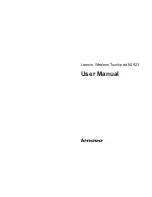
Wiring a Power Connection
To use the 2-pin 3.5 mm mini-Phoenix connector with a 12 VDC-compliant power supply, the
incoming PWR and GND wires from the external source must be connected to their
corresponding locations on the connector (FIG. 4).
1.
Insert the PWR and GND wires on the terminal end of the 2-pin 3.5 mm mini-Phoenix
cable.
Match the wiring locations of the +/- on both the power supply and the terminal
connector.
2.
Tighten the clamp to secure the two wires.
Do not tighten the screws excessively;
doing so may strip the threads and damage the connector.
3.
Verify the connection of the 2-pin 3.5 mm mini-Phoenix to the external 12 VDC-
compliant power supply.
Wiring the NXA-AVB/ETHERNET Connectors and Cables
The inputs and outputs on the breakout box are separated into front and rear connectors.
The rear connectors are used to input external signals. The front connectors are used to
communicate signals between the NXA-AVB and a target panel. FIG. 5 provides a layout of
the wiring connection both into and from the breakout box.
Power should be applied to the NXA-AVB/ETHERNET only after all connections have
been secured onto both the box and target panel.
Use a standard CAT5 Ethernet cable (connected to the rear of the Panel) to provide
communication and 10/100 network connectivity between the panel, breakout box, NetLinx
Master, and the network. The rear-panel wiring connections are described below (from left to
right):
Wiring for Unbalanced Audio
Use FIG. 6 to configure an unbalanced audio connection.
Wiring for Balanced Audio
Use FIG. 7 to configure a balanced audio connection.
Modero Setup and System Connection
1.
Carefully remove the panel from the shipping box, peel the protective plastic cover
from the LCD and apply power to the panel.
2.
From below the LCD, press the grey Front Setup Access button for 6 seconds (pass-
ing-over the Setup page) to access the Calibration setup page and follow the on-
screen instructions.
3.
Press the on-screen
Protected Setup
button on the Setup page.
4.
Enter the panel password into the keypad (default is
1988)
.
5.
Press the
Device Number
field to open the on-screen Device Number keypad and
enter a value for the panel (
default is 10001
).
6.
Press
Done
when finished and press the on-screen
Reboot
button to cycle power to
the panel.
7.
Press the grey Firmware Setup Access button for 3 seconds to open the Setup page
and touch the on-screen
Protected Setup
button.
8.
Repeat step 4 to continue to the Protected Setup page.
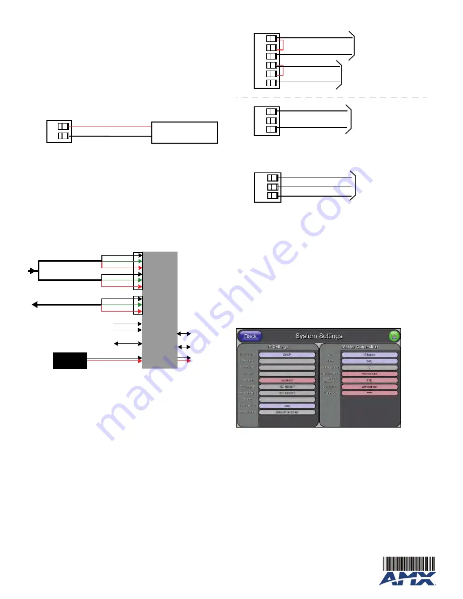
9.
Press the
System Settings
button to open the System Settings page (FIG. 8).
10.
Toggle the
DHCP Static
field to
DHCP
.
11.
Toggle the
Type
field to
Ethernet
.
12.
Toggle the
Mode
field to
URL
.
13.
Enter both the System Number and IP Address of the target Master.
14.
Enter a valid Username and/or Password if the target Master is secured.
15.
Press the
Back
button and then press the on-screen
Reboot
button to save any
changes and cycle power.
Additional Documentation
For more detailed installation, configuration, programming, file transfer, and operating
instructions, refer to the
NXD-CV10/NXT-CV10
Instruction Manual, available on-line at
www.amx.com.
FIG. 4
NetLinx power connector wiring diagram
FIG. 5
NXA-AVB/ETHERNET Breakout Box connector wiring diagram
AUDIO IN:
6-pin mini-Phoenix connector, divided into left and right audio channels.
Each channel is divided into GND, IN+, and IN- terminal cable connec-
tors (2 sets of 3 for each channel).
MIC OUT:
4-pin mini-Phoenix connector, divided into GND, OUT-, and OUT+
terminal connectors.
Video In BNCs:
Feeds either Composite/S-Video Luma or S-Video Chroma signals into
the NXA-AVB/ETHERNET. This feed is then redirected out to a Modero
panel through the front Audio/Video CAT5 port.
ETHERNET:
RJ-45 connector routes data to the G4 touch panel through the front
Ethernet port. These connections use a standard CAT5 Ethernet cable to
provide communication between the target touch panel, Breakout Box,
and NetLinx Master.
PWR:
2-pin mini-Phoenix connector that connects to a PSN power supply. This
port can be used to provide power to a Modero panel by sending it
through the NXA-AVB/ETHERNET (rear power connector through to the
front power connector).
PWR +
GND -
To the Touch Panel
Power Supply
NX
A-A
VB/
ETH
ERNE
T
Br
ea
kou
t Bo
x
Ethernet
(RJ-45)
Comp/Y (BNC)
C (BNC)
Audio In -
Left Channel
(6-pin captive wire)
Audio In -
Right Channel
(6-pin captive wire)
GND
In (-)
In (+)
GND
In (-)
In (+)
GND(-)
Out (-)
Out (+)
Microphone Out
(4-pin captive wire)
Power
Ethernet Out
(CAT5)
Audio/Video
(CAT5)
Power to
touch panel
F
R
O
N
T
R
E
A
R
supply
FIG. 6
Wiring the rear AUDIO IN and MIC OUT for use with Unbalanced Audio
FIG. 7
Wiring the rear AUDIO IN and MIC OUT for use with Balanced Audio
FIG. 8
Sample System Settings page
Unbalanced
IN
GND
IN-
IN+
GND
IN-
IN+
Left Channel
Right Channel
(Jumper IN- to GND)
Unbalanced
OUT
GND
OUT-
OUT+
Microphone
Unbalanced
IN
(Jumper IN- to GND)
AUDIO IN
MIC OUT
Balanced
OUT
GND
OUT-
OUT+
Ground signal
Return signal
Line signal
Panel’s connection information
NetLinx Master’s
connection information