background image

Installation

18

 MXD/T-2000XL-PAN 20.3" Modero X Series® Panoramic Touch Panels

Installation Recommendations

During any installation, a lack of ventilation may produce conditions that may adversely affect the device’s 
operation. In these circumstances, special care must be made to make sure that temperatures within enclosed 
areas do not exceed the device’s maximum rated temperature. 

MXD-2000XL-PAN Installation

The MXD-2000XL-PAN may be installed directly into a solid surface environment, using either solid surface 
screws or the included locking tabs for different mounting options. Once installed, the MXD-2000XL-PAN is 
contained within a clear outer housing known as the back box. This back box is removed when installing the 
device into a wall or into a Rough-In Box.

Installing the MXD-2000XL-PAN into a wall

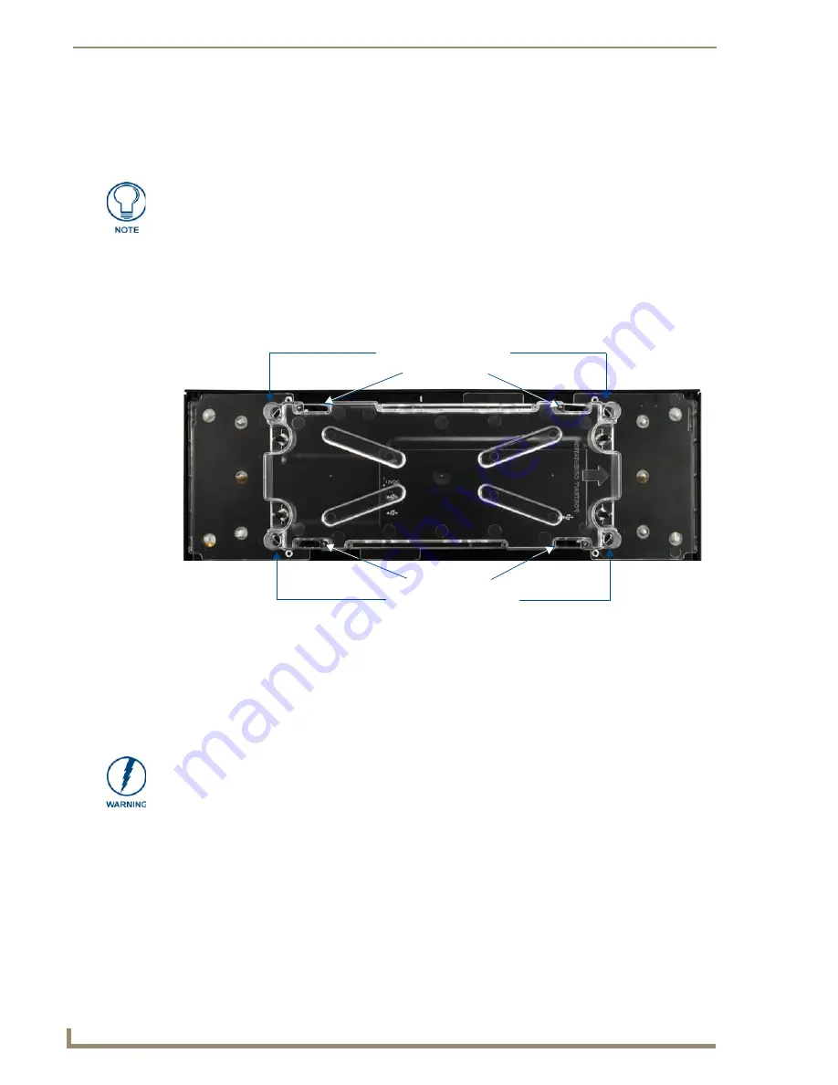
The MXD-2000XL-PAN comes with a clear plastic backbox (FIG. 14) designed to attach the panel to most 
standard wall materials. This backbox has four locking tabs (two on top and two on bottom) to help lock the 
backbox to the wall. These locking tabs are only extended AFTER the backbox is inserted into the wall. 

The backbox also has four slots for accepting the temporary mounting posts mounted on the back of the device 
(FIG. 15 and FIG. 16).


While the outside temperature of the device may be at or below its maximum 
operating temperature, special care must be taken before and during installation to 
ensure that the maximum operating temperature is not exceeded within wall or rack 
installation spaces.

FIG. 14  

MXD-2000XL-PAN Back Box

Locking Tabs

Locking Tabs

Temporary Mounting Posts

Temporary Mounting Posts

When installing the backbox, make sure that the assembly is in the correct position 
and in the correct place. Once the locking tabs are extended and locked into place, 
removing the backbox may be difficult without having access to the back of the wall 
or causing damage to the wall. 

Summary of Contents for Modero MXT-2000XL-PAN

Page 1: ...Operation Reference Guide Touch Panels MXT D 2000XL PAN 20 3 Modero X Series Panoramic Tabletop Touch Panel 20 3 Modero X Series Panoramic Wall Touch Panel Last Updated 10 24 2012 ...

Page 2: ...rked on the outside of each box The RMA is valid for a 30 day period After the 30 day period the RMA will be cancelled Any shipments received not consistent with the RMA or after the RMA is cancelled will be refused AMX is not responsible for products returned without a valid RMA number AMX is not liable for any damages caused by its products or for the failure of its products to perform This incl...

Page 3: ...MPLIED WARRANTIES OF MERCHANTABILITY AND FITNESS FOR A PARTICULAR PURPOSE WITH REGARD TO THE AMX SOFTWARE THIS LIM ITED WARRANTY GIVES LICENSEE SPECIFIC LEGAL RIGHTS Any supplements or updates to the AMX SOFTWARE including without limitation any if any service packs or hot fixes provided to Licensee after the expiration of the ninety 90 day Limited Warranty period are not covered by any warranty o...

Page 4: ......

Page 5: ...Memory 8 Basic Operation 8 Powering on the MXD 2000XL PAN 8 Microphone 8 Audio Video Capabilities 8 MXD 2000XL PAN NC 9 MXD T 2000XL PAN Features 10 Picture View 10 Preview Mode and Normal Mode 11 Picture View Send Command 12 Configuration 12 Bluetooth Support 12 NFC 12 Cleaning the Touch Overlay and Case 13 Installation 15 MXT 2000XL PAN Installation 15 Wiring Guidelines 15 Wiring a Power Connect...

Page 6: ...ve 27 Transfer the Firmware File From the Flash Drive to the Touch Panel 28 Upgrading from Previous Firmware 29 Returning to Factory Default Firmware 29 Upgrading Firmware Via NetLinx Studio 30 Viewing devices on the Virtual System 32 Downloading firmware 32 Appendix Troubleshooting 35 Overview 35 Panel Doesn t Respond To Touches 35 Panel Isn t Appearing In The Online Tree Tab 35 Can t Connect To ...

Page 7: ...peer communication by sharing pairing and transaction between RF devices like exchanging data identities Enhanced Usability External phone connections via Bluetooth or USB and HD video streaming Graphic Leaps Bounds The Modero X Series includes some striking new intuitive UI functionality including gesturing swiping dynamic reordering and enhanced animation capabilities Perfect From Any Angle Incl...

Page 8: ...0 4 x 9 5 519 mm x 242 mm 21 3 541 mm diagonal display with a viewable area of 18 7 x 7 8 475 mm x 198 mm 20 3 514 mm The device communicates via Ethernet 10 100 port RJ 45 connector supported IP and IP based protocols UCP TCP ICMP ICSP IGMP DHCP Telnet FTP DNS RFB for VNC and HTTP and USB 3 USB host 2 0 Type A ports and 1 Micro USB device port The MXT 2000XL PAN also supports Near Field Communica...

Page 9: ...gs Pages Microphone 42dB 3dB sensitivity FET microphone Speakers 4 ohm 2 Watt 300Hz cutoff frequency Camera HD 720P camera for video conferencing video chat support Rear Panel Components USB connections 2 easily accessible USB ports on rear of base used for connection to keyboard mouse or USB drive Underside Panel Components Ethernet 10 100 Port 10 100 Base T RJ 45 connector for Ethernet connectiv...

Page 10: ...V MP3 Intercom Full Duplex VoIP SIP v2 0 supported with AMX CSG Operating Environment Operating Temperature 32 F to 104 F 0 C to 40 C Storage Temperature 4 F to 140 F 20 C to 60 C Humidity Operating 20 to 85 RH Humidity Storage 5 to 85 RH Dimensions HWD 9 1 4 x 20 7 16 x 5 7 8 234 mm x 519 mm x 149 6 mm Weight 12 2 lbs 5 53 Kg Certifications FCC Part 15 Class B C Tick CISPR 22 Class B CE EN 55022 ...

Page 11: ...s the Sleep button on the top of the device FIG 1 If the device has gone into its Sleep Mode a touch of the touchscreen or of the Sleep button will reactivate it Powering on the MXT 2000XL PAN The MXT 2000XL PAN may be powered on by touching and holding the Sleep button on the top of the device Microphone The MXT 2000XL PAN contains a built in microphone above the touch screen for video and audio ...

Page 12: ...sed to manage systems throughout the house The MXD 2000XL PAN features a 20 4 x 9 5 519 mm x 242 mm 21 3 541 mm diagonal display with a viewable area of 18 7 x 7 8 475 mm x 198 mm 20 3 514 mm diagonal The device communicates via Ethernet 10 100 port RJ 45 connector supported IP and IP based protocols UCP TCP ICMP ICSP IGMP DHCP Telnet FTP DNS RFB for VNC and HTTP and USB 2 USB host 2 0 Type A port...

Page 13: ...tt 300Hz cutoff frequency Camera landscape only HD 720P camera for video conferencing video chat support Rear Panel Components Ethernet 10 100 Port 10 100 Base T RJ 45 connector for Ethernet connectivity Power Port Locking 2 Pin 3 5mm captive wire connector Micro USB Port 5 pin Micro USB connector used for video output from camera video Landscape Only and microphone output only Touch Panel Display...

Page 14: ... 10 100 port RJ 45 connector USB 2 USB host 2 0 Type A ports Near Field Communications NFC Supports standards ISO IEC 15693 ISO IEC 14443A ISO IEC 14443B Unique Identifier UID Typical Range 25 Maximum Range 5 Bluetooth HID Profile v1 1 Keyboard Mouse Support requires MXA BT Bluetooth Adaptor Video Streaming File Formats MPEG TS for MPEG2 HTTP for MJPEG Video Conferencing External application using...

Page 15: ...X Series Panoramic Touch Panels MXD 2000XL PAN NC The MXD 2000XL PAN P NC FG5968 33 and MXD 2000XL PAN L NC FG5968 34 No Comm touch panels do not have camera microphone or NFC capability These otherwise have all of the functionality of the MXD 2000XL PAN panels ...

Page 16: ... page To start Picture View 1 Connect a USB drive to the device Picture View will automatically recognize all available images on the drive and start displaying them on the touchscreen 2 When the images begin to display touch any place on the touchscreen to open the configuration popup menu FIG 7 If no selection is made this menu will remain in place for 15 seconds and then disappear It may be acc...

Page 17: ...of seconds a selected image will be displayed in Picture View This may be selected between 5 10 15 30 and 60 seconds 6 The counter beneath the buttons displays the number of current images being displayed by the MXT 2000XL PAN versus the number detected on the USB drive Preview Mode and Normal Mode Picture View has two modes Preview Mode and Normal Mode Preview Mode allows the user to configure Pi...

Page 18: ...w centimeters working with existing contactless card technologies and containing built in capabilities to support secure applications By using NFC technology users may receive access to touch panels and touch panel pages through access badges and other card options The maximum range for the NFC antenna is 0 5 12 7 mm but the typical usage range is 0 25 6 35 mm The antenna itself is accessible from...

Page 19: ...f cleaning fluid specifically for use with the device When cleaning the device do not directly spray the device with cleaning fluid Instead spray the cloth and then apply the cloth to the touch screen Do NOT use abrasives of any type to clean the device as abrasives may permanently damage or remove the device s finish FIG 8 NFC antenna location on the MXT 2000XL PAN 3 25 82 55 mm 0 375 9 53 mm NFC...

Page 20: ...Modero X Series Touch Panels 14 MXD T 2000XL PAN 20 3 Modero X Series Panoramic Touch Panels ...

Page 21: ... power Ethernet and Micro USB cables FIG 10 Each channel side has slots for attaching tie wraps to secure each cable The ferrite on the power cable must be secured with the included tie wrap during installation to prevent the possibility of the panel not sitting flush on the table Other cables may be secured with tie wraps if desired but this is not necessary Wiring Guidelines The MXT 2000XL PAN u...

Page 22: ...ing locations of the on both the power supply and the terminal connector 2 Tighten the clamp to secure the two wires Do not tighten the screws excessively doing so may strip the threads and damage the connector 3 Verify the connection of the 2 pin 3 5 mm captive wire to the external 12 VDC compliant power supply and apply power Connecting power to the MXT 2000XL PAN should be done using the includ...

Page 23: ...wall with a filled volume such as with insulation or concrete as well as with a closed volume such as between studs in an otherwise finished wall The diagram shows how heat generated by the device or other devices may have no way to escape and may build up to levels that may affect device operation In FIG 13 the diagram displays an AMX device in a typical rack mounting with full air circulation ar...

Page 24: ...ear plastic backbox FIG 14 designed to attach the panel to most standard wall materials This backbox has four locking tabs two on top and two on bottom to help lock the backbox to the wall These locking tabs are only extended AFTER the backbox is inserted into the wall The backbox also has four slots for accepting the temporary mounting posts mounted on the back of the device FIG 15 and FIG 16 Whi...

Page 25: ...w of installed MXD 2000XL PAN Portrait Wall Temporary Mounting Posts MXD 2000XL PAN front Back Box Back box knockouts Wall Back box knockouts Locking tabs MXD 2000XL PAN front In order to guarantee a stable installation of the MXD 2000XL PAN the thickness of the wall material must be a minimum of 50 inches 1 27cm and a maximum of 875 inches 2 22cm ...

Page 26: ...k in the wiring to accommodate any re positioning of the panel The maximum recommended torque to screw in the locking tabs on the plastic back box is 5 IN LB 56 N CM Applying excessive torque while tightening the tab screws such as with powered screwdrivers can strip out the locking tabs or damage the plastic back box FIG 17 MXD 2000XL PAN Template 20 433 519 00 mm 9 53 242 00 mm 14 50 368 30 mm 5...

Page 27: ...the back box into the wall opening Insure that the locking tabs lie flush against the back box FIG 18 MXD 2000XL PAN Back Box installation Landscape FIG 19 MXD 2000XL PAN Back Box installation Portrait Cables routed to wall opening Knockouts top Mounting screw placement optional Back box cutout Outer edge of back box Locking tab Cables routed to wall opening Outer edge of back box Back box cutout ...

Page 28: ... touch panel make sure that these are flush with the back box 9 Insert each connector into its corresponding location along the back of the device FIG 20 10 Test the incoming wiring by attaching the panel connections to their terminal locations and applying power Verify that the panel is receiving power and functioning properly to prevent repetition of the installation 11 Insert the four temporary...

Page 29: ...ero X Series Panoramic Touch Panels FIG 21 MXD 2000XL PAN installation Landscape FIG 22 MXD 2000XL PAN installation Portrait Mounting posts Side cover Mounting post openings Wall Mounting post openings Wall Side cover Side cover Screws Screws ...

Page 30: ...ure a connection to the device so make sure to insert and tighten the screws before applying power 1 Insert the PWR and GND wires on the terminal end of the 2 pin 3 5 mm captive wire cable Match the wiring locations of the on both the power supply and the terminal connector 2 Tighten the clamp to secure the two wires Do not tighten the screws excessively doing so may strip the threads and damage t...

Page 31: ...dero X Series Programming Guide Information on Settings pages panel configuration and programming is included in the Modero X Series Programming Guide available at www amx com Programming the MXT 2000XL PAN and MXD 2000XL PAN require the use of the latest versions of NetLinx Studio and TPDesign 4 both available at www amx com ...

Page 32: ...Configuration and Programming 26 MXD T 2000XL PAN 20 3 Modero X Series Panoramic Touch Panels ...

Page 33: ...require removing the panel from the wall mount if a USB extension was not already installed 2 Create a directory on the USB flash drive with one of the following names depending on the panel you are upgrading Note that the name must match exactly do not include the quotes These directory names are not case sensitive 3 Copy the firmware kit file to be transferred for example SW5968_ModeroX_v2_103_5...

Page 34: ...y require entering a password c From the Configuration page select Admin d From the Admin Configuration page select Install Firmware 3 In the Firmware Installation page select New to install new firmware from external disk 4 The popup page displays the name of the firmware file for example SW5968_ModeroX_v2_103_52 kit 5 Select Yes and follow the directions displayed on the popup 6 Once the panel r...

Page 35: ...oose Yes the device will retrieve the files and then reboot Returning to Factory Default Firmware The MXT 2000XL PAN and MXD 2000XL PAN allow the option to return the device to its original factory default firmware which may be necessary in certain situations To return the device to its factory default firmware 1 From the Settings page select the Configuration page 2 From the Configuration page se...

Page 36: ...lick on the NetLinx Master radio button from the Platform Selection section 4 Click on the Virtual Master radio box from the Transport Connection Option section to configure the PC to communicate directly with a panel Everything else such as the Authentication is greyed out because this connection is not going through the Master s UI 5 Click the Edit Settings button on the Communications Settings ...

Page 37: ...dio application 11 Click the OnLine Tree tab in the Workspace window to view the devices on the Virtual System The default System value is 1 12 Right click on the Empty Device Tree System entry and select Refresh System to re populate the list 13 The Online Tree should now display the connection to the device The Connection Status Icon on the device may take up to five seconds to register the conn...

Page 38: ...he Modero Kit file to a known location 3 Select Tools Firmware Transfers Send to NetLinx Device from the main menu to open the Send to NetLinx Device dialog FIG 33 Verify that the panel s System and Device number values match those values listed within the System folder in the Online Tree tab of the Workspace window 4 Select the appropriate Kit file from within the Browse for Folder window FIG 34 ...

Page 39: ...ick Send to begin the transfer The file transfer progress is indicated on the bottom right of the dialog 9 After the file transfer is complete the panel will automatically reboot 10 After the panel has finished rebooting right click the associated System number and select Refresh System This causes a refresh of all project systems establishes a new connection to the Master and populates the System...

Page 40: ...Upgrading Firmware 34 MXD T 2000XL PAN 20 3 Modero X Series Panoramic Touch Panels ...

Page 41: ...able and to reply with a connection failure instantly if it is not Without using the ping feature a connection may still be attempted but a failure will take longer to be recognized When connecting to a NetLinx Master controller via TCP IP the program will first try to ping the controller before attempting a connection Pinging a device is relatively fast and will determine if the device is off lin...

Page 42: ...Appendix Troubleshooting 36 MXD T 2000XL PAN 20 3 Modero X Series Panoramic Touch Panels ...

Page 43: ...Appendix B Troubleshooting 37 MXD T 2000XL PAN 20 3 Modero X Series Panoramic Touch Panels ...

Page 44: ...registered trademarks of AMX AMX reserves the right to alter specifications without notice at any time It s Your World Take Control 3000 RESEARCH DRIVE RICHARDSON TX 75082 USA 800 222 0193 469 624 8000 469 624 7153 fax 800 932 6993 technical support www amx com ...

Reviews: