

For full warranty information, refer to the AMX Instruction Manual(s) associated with your Product(s).
6/13
©2013 AMX. All rights reserved. AMX and the AMX logo are registered trademarks of AMX.
AMX reserves the right to alter specifications without notice at any time.
3000 RESEARCH DRIVE, RICHARDSON, TX 75082 • 800.222.0193 • fax 469.624.7153 • technical support 800.932.6993 • www.amx.com
93-5968-01
REV: D
NOTE:
The MXT-2000XL-PAN-NC (
FG5968-32
) No Comm touch panel does not have
camera, microphone, or NFC capability. It otherwise has all of the functionality of the MXT-
2000XL-PAN panel.
Panel Connectors and Wiring
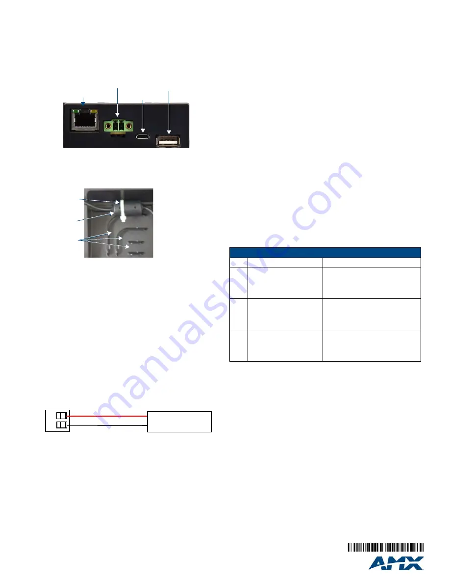
FIG. 2 shows the connectors located on the underside of the MXT-2000XL-PAN. The
Micro-USB port is used for camera video output. The underside USB port, as well as
the two rear USB ports, may be used with a flash drive for page transfers, firmware
upgrades, or Picture View. Any USB peripherals (mouse, keyboard, etc.) may be
connected to one of the two USB ports on the rear of the device.
The MXT-2000XL-PAN does not have individual channels on the base of the device to
allow passage of cables from underneath the base. Instead, it has one slot at the base
to allow options on cable configuration, with channels for securing power, Ethernet,
and Micro-USB cables (FIG. 3).
Each channel side has slots for attaching tie-wraps to secure each cable. The ferrite
on the power cable must be secured with the included tie-wrap during installation to
prevent the possibility of the panel not sitting flush on the table.
Wiring Guidelines
The MXT-2000XL-PAN uses a 12 VDC-compliant power supply to provide power to
the panel via the 2-pin 3.5 mm captive wire PWR connector. Use the previously
provided power requirement information to determine the power draw. The incoming
PWR and GND wires from the power supply must be connected to the corresponding
locations within the PWR connector.
NOTE
: Apply power to the panel only after installation is complete.
NOTE
: Connecting power to the MXT-2000XL-PAN should be done using the included
2-pin 3.5mm captive wire connector included with the device. This connector is
retained within its port with locking screws instead of the pins on each side of standard
captive wire connectors, and using force to insert a standard captive wire connector
may damage the device
.
Wiring a Power Connection
To use the 2-pin 3.5 mm captive wire connector with a 12 VDC-compliant power
supply, the incoming PWR and GND wires from the external source must be
connected to their corresponding locations on the connector (FIG. 4).
The connector
uses locking screws to insure a connection to the device, so make sure to insert and tighten
the screws before applying power.
1.
Insert the PWR and GND wires on the terminal end of the 2-pin 3.5mm captive
wire connector cable.
Match the wiring locations of the +/- on both the power
supply and the terminal connector.
2.
Tighten the clamp to secure the two wires.
Do not tighten the screws
excessively; doing so may strip the threads and damage the connector.
3.
Verify the connection of the 2-pin 3.5 mm captive wire connector cable to the
external 12 VDC-compliant power supply and apply power.
Configuring the MXT-2000XL-PAN
The MXT-2000XL-PAN is equipped with Settings Pages that allow you to set and
configure various features on the panel. For more information on connecting and
configuring the MXT-2000XL-PAN to a network, please refer to the
Modero X Series
Programming Guide
, available at
www.amx.com
.
Accessing the Settings Pages
To access the Settings Pages on the MXT-2000XL-PAN, press and hold the
Sleep
Button (FIG. 1) on the top of the panel for 3 seconds. The user will be prompted to
release the button to enter the
Settings
page.
Accessing The Configuration Page
1.
From the
Settings
Page, select
Configuration
. If the
Configuration
page is
password protected, this opens a password keypad.
2.
Enter the panel password into the keypad (the default is
1988)
and select
Ok
to
access the page.
Setting the Panel’s Device Number and Device Name
In the
Configuration
page:
1.
Press
Panel
to open the
Panel Configuration
page.
2.
Ensure that the
Synchronize Device Names
button is not selected, and click it to
deselect it if it is.
3.
Press
Device Number
to open the Device Number keypad.
4.
Enter a unique Device Number assignment for the panel and press
OK
.
5.
Press the
Device Name
field to open the Device Name keypad.
6.
Enter a unique Device Name assignment for the panel and press
OK
.
7.
Click the arrow on the top left of the page once to return to the
Configuration
page and twice to return to the
Settings
page.
Accessing The Connection & Networks Page
1.
From the Settings Page, select
Connection & Networks
. If the page is password
protected, this opens a password keypad.
2.
Enter the panel password into the keypad (the default is
1988)
and select
Ok
to access
the page.
Connecting To a Master
The panel requires that you establish the type of connection you want to make
between it and your master.
In the
Connection & Networks
page:
1.
Select
Master Connection
to open the
Master Connection
page
2.
Press
Mode
to toggle through the available connection modes:
3.
If you have enabled password security on your master, you need to set the username
and password within the device.
a. Select
Username
to open the Master User keyboard.
b. Set your Username and select
Ok
.
c. Select the
Password
to open the Master Password keyboard.
d. Set your Master Password and select
Ok
.
e. Press the
Back
button twice to return to the
Settings
page.
Configuring the Panel to a Network
The first step is to configure the panel’s communication parameters. This only
configures the panel to communicate with a network, and it is still necessary to tell the
panel with which Master it should be communicating.
Network Communication With a DHCP Address
In the
Connection & Networks
page:
1.
Select
Network Connection
to open the
Network Connection page.
2.
Toggle the
DHCP/Static
field until the choice cycles to
DHCP
. This action causes
all fields on the page (other than
Host Name
) to be greyed-out.
3.
Select
Host Name
to open the Host Name keyboard. Enter the new host name
and click
OK
.
FIG. 2
Rear connectors
FIG. 3
Tie-wrap for power connector ferrite
FIG. 4
NetLinx power connector wiring diagram
Ethernet 10/100
Port
Micro-USB
Port
USB Port
12 VDC
Power Port
Tie-wrap channels
Tie-wrap
Ferrite
PWR +
GND -
To the Touch Panel
Power Supply
Connection Modes
Mode
Description
Procedures
Auto
The device connects to the first
master that responds.
This setting requires that you set
the System Number.
Setting the System Number:
1. Select Master System Number to open
the keypad.
2. Set your Master System Number and
select
Ok
.
URL
The device connects to the
specific IP of a master via a TCP
connection.
This setting requires that you set
the Master’s IP.
Setting the Master IP:
1. Select the Master IP number to the
keyboard.
2. Set your Master IP and select
Ok
.
Listen
The device “listens” for the
master to initiate contact.
This setting requires you provide
the master with the device’s IP.
Confirm device IP is on the Master URL list.
You can set the Host Name on the device
and use it to locate the device on the master.
Host Name is particularly useful in the DHCP
scenario where the IP address can change.


