

Installation Guide
MAX-AOM Audio-Only Module
MAX-AOM Audio-Only Module
The MAX-AOM Audio-Only Module (FIG. 1) is a streaming audio playback USB
module that distributes up to four stereo outputs (both digital and analog).
The AOM is available either as a single unit (
FG 2178-55
), or as two units using the
optional AOM-EX Expansion Kit (
FG 2178-56
) that mount side-by-side within a single
rack unit. The AOM-EX adds another four audio outputs, to allow up to eight audio-only
outputs. Note that the AOM-EX does not include a faceplate.
•
The MMS-01S, MMS-02S and MMS-02SB servers feature two built-in audio out-
put channels, and support one MAX-AOM (for a maximum total of six audio out-
put channels).
•
The MMS-04S, MMS-12S and MMS-900 servers support two MAX-AOMs (for a
maximum total of eight audio output channels).
Note:
Do not use a USB hub with MMS servers or AOM modules.
Product Specifications
Adding the MAX-AOM to the MMS Server
In order for AOM(s) to be recognized by the MMS server, they must each be added to
the system, via the
Add Output Module
options in the MAX Admin Menu.
Add the AOM(s) to the server (as described below) before physically connecting the
module(s).
Since AOMs provide up to four audio outputs per USB port on the MMS server, each
of the AOM audio outputs must be associated with a specific output/zone on the MMS
server:
Note:
The MMS-01S, -02S and 02SB servers feature two built-in audio outputs, which
occupy the first two outputs on (internal) USB 1 port for those servers. Refer to the
MMS-01S, -02S and -02SB Installation Guides for details on configuring the audio
outputs for external AOMs.
1.
Open the
System Information
tab in WinMAX, and click on the
Server
Configuration
button to access the
MAX Admin menu.
2.
Go to
Output Module Setup > Add Output Module > AOM
to access the
Enter
Output Number
dialog.
3.
Enter an available server output/zone number (
between 1 - 33
). This is the
Output Number that will appear in the WinMAX software.
Note
: The server will not allow you to assign an audio output to an output/zone
that is already in use. To determine which server outputs are already being used,
select
View
from the Output Module Setup menu.
•
If other output modules (AOM or AVM) have already been added to the server,
then assign the AOM to the next available output. For example, if you had
already added 10 output modules to the server, then this AOM should be
assigned to output 11.
•
Note that AOMs use up to 4 outputs on the MMS server, while AVMs use only
one.
•
If you are adding only one AOM module to the server, then you’ll specify up to
four server output/zones (one for each of the four possible audio outputs on the
AOM). If you are adding two AOMs (MMS-04S, -12S and -900 servers only),
you’ll specify up to eight outputs (four per AOM), as indicated in the following
t
able.
4.
In the
Enter USB port number
field, enter the number of the USB port on the
MMS server that this AOM will be connected to (
range = 1 - 2
). If you are using a
MMS-01S, -02S or -02SB server, this number should always be set to
1
(since
these servers have only one USB port). Click
OK
to proceed.
5.
In the
Enter AOM output number
field, specify which of the four available audio
outputs on the AOM you are adding (
range = 1 - 4
) to the MMS server output
number specified in step 1.
6.
The system will notify you that the module has been added to the system. Click
OK
to return to the Output Module Setup menu.
Once the module has been added, select
View
from the Output Module Setup menu.
The module you just added should appear in the list of Installed Output Modules. AOM
modules are listed by MMS output /zone number assignment, USB port number and
AOM output number.
•
Select
View
from the Admin menu to view a list of all output modules (AOMs and
AVMs) already in the system.
•
Select
Remove
to remove an existing output module from the system.
Connecting to MMS Servers
Once the AOM has been added to the server, you can connect it to the MMS server
and audio system(s):
1.
Connect the AOM(s) to an audio system (amplifier, switcher, etc.) using one of
two options:
a) Use stereo RCA cables for analog audio output.
b) Use a coaxial cable for digital audio output.
2.
Connect the included power supply to the rear panel power connector on the
AOM to apply power to the module.
3.
Use the supplied 6’ USB cable to connect a USB port on the rear panel of the
MMS server to the USB port on the rear panel of the MAX-AOM module.
Additional Information on USB Ports 1 and 2 (on the MMS-04S, MMS-12S
and MMS-900 Servers)
If you are using both USB connectors on the MMS server, be sure to note which audio
zones are associated with the AOM connected to each USB port:
•
The USB 1 port is for audio outputs 1 through 4.
•
The USB 2 port is for audio outputs 5 through 8.
In this scenario, if the AOM connected to USB port 1 on the server (providing AOM
outputs 1-4) is unplugged or experiences any other failure, then USB port 2 takes over
and behaves like port 1.
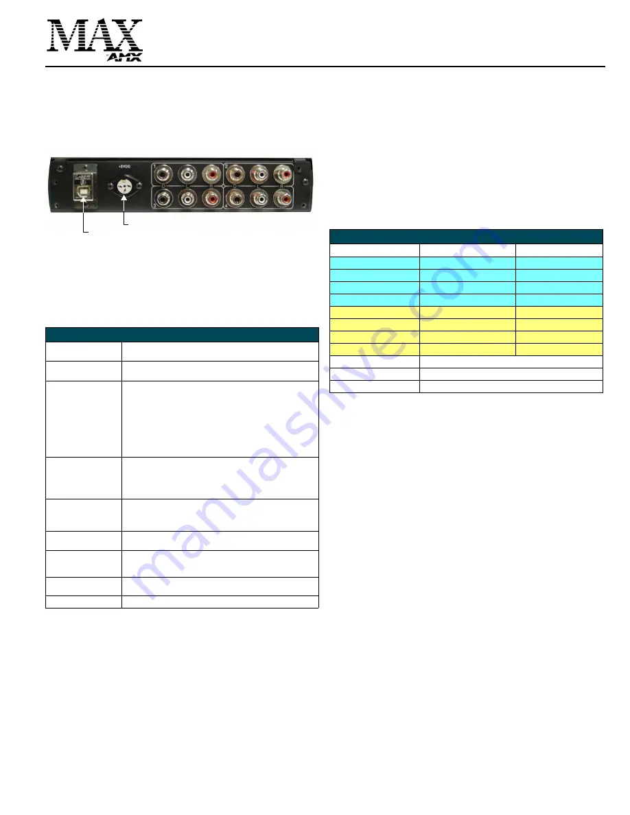
FIG. 1
MAX-AOM Audio-Only Module - rear panel connectors
MAX-AOM (FG 2178-55) Specifications
Power:
• 5VDC 0.9A external power supply
• 110-240 VAC 50/60 Hz
AC Current Draw (AMP):
• .09A - Bootup/Power Cycle Peak
• .09A - Normal Usage Peak
Audio Output:
• 4 audio output channels, each with RCA SPDIF digital, analog
stereo
• Digital audio output: 6-channel Dolby Digital and DTS
• Analog audio output: stereo
• 24-bit D/A conversion, 128X over sampling
• 48kHz sampling rate
• Output level -10dBV nominal
• Signal to Noise Ratio 110db A-weighted
• Frequency Response: 20Hz to 20kHz
• Dynamic Range: 110dB
Rear Panel Connectors:
• USB Connector: USB connector (Type B)
• Power Cable connector: DC 3-pin DIN.
• Audio Outputs: Four sets of three connectors (see FIG. 1):
- (D): One RCA S/PDIF (coax) connector for digital output.
- (L, R): Two RCA connectors for stereo analog output.
Dimensions (HWD)
• MAX-AOM (only): 1.75” x 8.48” x 10.47”
(4.44cm x 21.53cm x 26.59cm)
• Two MAX-AOM(s) with AOM-EX Rack Mount Kit:
1.75” x 19.1” x 12.02” (4.44cm x 48.51cm x 30.53cm)
Weight:
• MAX-AOM: 10.00 lbs (4.53 kg)
• MAX-AOM-EX: 8.45 lbs (3.83 kg)
Included Accessories:
• 5VDC 2.4A external power supply
• 6’ (1.83m) USB (A to B) cable
• Removable Faceplate
Optional Accessories
• AOM-EX Expansion Kit (
FG 2178-56
): includes a second MAX-
AOM unit with mounting brackets and hardware.
Certification:
FCC, CE
(rear)
Power Connector
USB connector (to MMS server)
OUTPUT 2
OUTPUT 1
OUTPUT 3
OUTPUT 4
MMS Output Zones, USB Port and AOM Audio Outputs
MMS Output/Zone (1-33)
USB port connection (1-2)
AOM Audio output (1-4)
1
AOM 1 (on USB 1)
AOM 1 - Audio Output 1
2
AOM 1 (on USB 1)
AOM 1 - Audio Output 2
3
AOM 1 (on USB 1)
AOM 1 - Audio Output 3
4
AOM 1 (on USB 1)
AOM 1 - Audio Output 4
5
AOM 2 (on USB 2)
AOM 2 - Audio Output 1
6
AOM 2 (on USB 2)
AOM 2 - Audio Output 2
7
AOM 2 (on USB 2)
AOM 2 - Audio Output 3
8
AOM 2 (on USB 2)
AOM 2 - Audio Output 4
9
AVM 1
10
AVM 2
11...(to 33)
AVM 3...


