

For full warranty information, refer to the AMX Instruction Manual(s) associated with your Product(s).
11/10
©2010 AMX. All rights reserved. AMX and the AMX logo are registered trademarks of AMX.
AMX reserves the right to alter specifications without notice at any time.
3000 RESEARCH DRIVE, RICHARDSON, TX 75082 • 800.222.0193 • fax 469.624.7153 • technical support 800.932.6993 • www.amx.com
93-UDM-RX02
REV: J
The Serial port can also be used as a control port for sending serial data to a connected
device. In this mode the UDM-RX02N supports baud rates from 1200 - 115200. If a display
device is controlled using a serial connection instead of IR, then a serial cable is connected
from the UDM-RX02N to the serial port on the display device.
Note
: The baud rate on the UDM-RX02N must match the baud rate as the receiver is set up
for. For example, if the baud rate has been changed to 115200 for a certain display, then
you’ll need to change your terminal to the same 115200 baud rate.
Depending on the screen manufacturer, it may be necessary to introduce a cross into this
connection by instead using the FG-RS02 cable, or a null modem DB9-DB9 adaptor with the
FG-RS01. In some cases the null modem adaptor may need a link between RTS/CTS at the
DB9 end.
For example, NEC LCD panels act as DTE equipment and work with standard serial cable,
while Fujitsu and Panasonic Plasma screens act as DCE equipment and therefore require
cross connections.
Note
: Refer to the UDM-0808-SIG / UDM-RX02N Operation/Reference Guide for pinout
details on the SERIAL (RJ12) connector.
To connect to a display device using a serial cable:
1.
Connect a serial cable to the UDM-RX02N’s SERIAL port.
2.
Run the serial cable (observing distance limitations) to the display device’s serial port
and connect.
Note
: The serial cable must be pinned out according to the Manufacturer’s instructions.
Failure to do so will result in serial commands failing.
IR Receiver (IR Rx) Port
The
IR Rx
port is used to enable user control and the remote compensation of the video link
to the UDM, using the FG-UDM-RC10 and the FG-IR03.
Refer to the
Protocols and IR Learning
section of the UDM Hub’s
Operation/Reference Guide
for details for information on learning a device’s IR commands.
IR Transmit (IR Tx) Port
The
IR Tx
port issues IR commands from the UDM-RX02 to a controlled display device (TV
monitor or display). One IR display device can be connected to the RX02 via the IR Tx port,
and controlled via the UDM Hub’s WebConsole or via remote control.
Connecting an IR Device to the IR Tx Port
1.
Connect an IR01 Endeleo IR Emitter Module (FG-IR01) to the IR Tx port on the RX02.
Note
: Ensure the position of the device corresponds to the position assigned in the
Devices option of the UDM Hub’s WebConsole.
2.
Run the other end of the IR Emitter cable to the device’s IR sensor, and attach the IR
Emitter to the device’s sensor by removing the cover on the reverse side of the IR
Emitter.
IR commands for each device on the system have to be learned by the UDM Hub in order to
function properly. Refer to the
Protocols and IR Learning
section of the UDM Hub’s
Operation/Reference Guide
for information on learning a device’s IR commands.
AUDIO Connectors
The UDM-RX02 provides standard Audio RCA output connectors for S/PDIF for digital audio,
and LEFT/RIGHT for analog audio output (FIG. 2).
VIDEO Connectors
VGA Input at Display Device
1.
Attach one end of the VGA cable to the
VGA
connector on the UDM-RX02.
2.
Run the other end to the VGA connector on the display device. Connect firmly.
3.
If appropriate connect audio to the audio connectors on the RX02.
Note
: Ensure the UDM Hub port the RX02 is attached to is configured correctly within
the Hub’s configuration software. Also ensure the correct Audio Type (Analog L/R, S/
PDIF, or None) is selected for the relevant input.
Composite Input at Display Device
1.
Attach the composite cable to the
CVBS
connector on the UDM-RX02.
2.
Run the other end of the composite cable to the Composite connector on the display
device. Connect firmly.
3.
If appropriate connect audio to the audio connectors on the RX02.
S-Video Input at Display Device
1.
Attach the SVideo cable to the
S Video
connector on the UDM-RX02.
2.
Run the other end of the SVideo cable to the SVideo connector on the display device.
Connect firmly.
3.
If appropriate connect audio to the audio connectors on the RX02.
Component Input at Display Device
1.
Attach the Component cables to the
Y
(green),
Pb
(blue) and
Pr
(red) connectors on
the UDM-RX02.
2.
Run the other end of the Component cable to the Component connectors on the dis-
play device. Connect firmly.
3.
If appropriate connect audio to the audio connectors on the RX02.
Video Compensation
Video at the Receive end can be compensated using three main methods;
•
Using the UDM Hub’s WebConsole
•
Using the UDM-RC02 Multi-Format IR Remote Control
•
Using a hyper terminal session via the serial connector on the RX02 (especially
effective setup method when using long runs)
Connecting an External IR Receiver Module
If passthrough mode (where a device such as a DVD or VCR can be controlled via a UDM-
RC02 Multi-Format IR Remote Control) is required then an IR03 External IR Receiver
Module will be needed to pick up IR controls from the remote control.
Additionally, if the RX02 is to be compensated via a remote control, then an IR Receiver
Module is also needed.
Connecting the UDM-RX02 Receiver to the UDM Hub
The RJ45 port on the front panel of the UDM Hub labelled “UDM” supports the UDM-RX02.
The RX02 is then connected to a display device.
1.
Connect a standard Cat5/6 Ethernet cable to the RJ45 port labelled
UDM
on the front
panel of the UDM Hub.
2.
Connect the other end of the Ethernet cable to the RJ45 port labelled
UDM
Hub
on the
rear panel of the RX02.
Note
: Ensure the UDM Hub port the RX02 is attached to is configured correctly within
the Hub’s configuration software. Also ensure the correct Audio Type (Analog L/R,
S/PDIF, or None) is selected for the relevant input.
UDM HUB Port LEDs
2 LEDs are visible at the
UDM Hub
port (on the UDM-RX02) when the UDM Hub is switched
on:
•
Green
– Connection to UDM Hub (if Cat 5 removed, LED switches off).
•
Amber
– Power (as well as comms if uploading protocols etc. the Amber LED may
flicker).
Powering on the UDM-RX02
Via the UDM-PS External Power Supply (Standard Installation)
The UDM-RX02 is typically powered via the included UDM-PS external 24 VDC power
supply power supply (FG-UDM-PS).
•
To connect the RX02 to the local power supply, insert the barrel connector of the power
supply into the power connector on the RX02.
•
To power down the RX02, remove the barrel connector of the power supply from the
power connector and then remove the Ethernet cable from the
UDM Hub
connector.
Via the UDM Hub
In installation scenarios where it is impractical to connect the UDM-PS power supply, the
RX02 may be also powered by its Hub device, via a standard CAT5 cable.
•
UDM Hubs can provide power to up to 10 (un-powered) RX02s.
•
Disconnecting the local power supply will not power down the UDM-RX02 if its
Ethernet connection to the UDM Hub is intact.
Note
: The UDM-PS Power supply should be used with any RX02 that is exhibiting video
noise at it’s display.
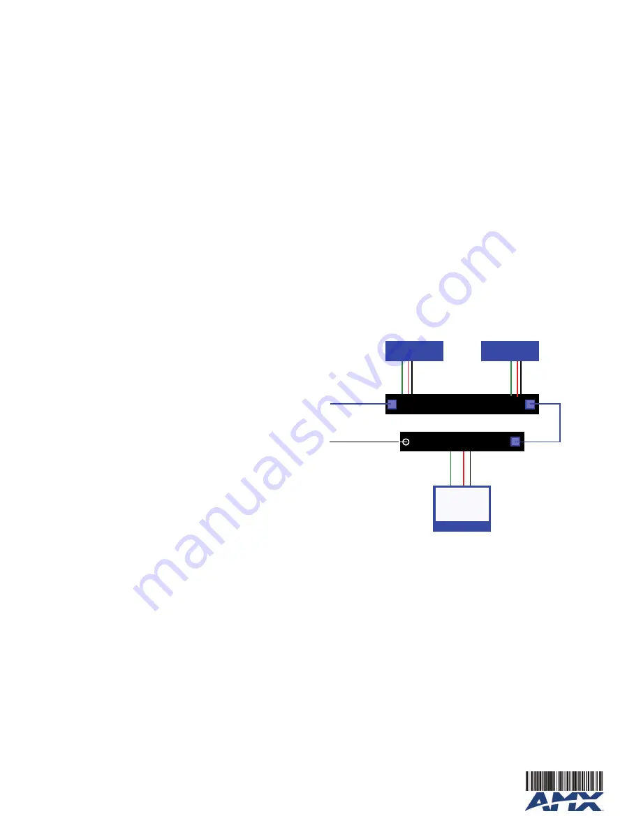
System Overview
FIG. 3 provides a basic system diagram representing a UDM Hub, UDM-RX02 Receiver, and
connected devices:
Additional Documentation
Refer to the
UDM-0102 and UDM-RX02 Multi-Format Distribution Hub and Receiver
Operation/Reference Guide
(available online at
www.amx.com
) for detailed information on
configuring the Hub, UDM receivers and source devices.
FIG. 3
UDM System Diagram
UDM Hub
UDM-RX02 Receiver
Display
Ethernet
(network)
Cat5
Video Out
Video In
Audio Out
Audio In
Video In
Audio In
Video Out
Audio Out
Video Out
Video In
Audio Out
Audio In
Power
(from UDM-PS)
DVD
DSS