


System Configuration Interface
190
Enova Digital Media Switchers - Hardware Reference Manual
Video Input and Output Details Windows
Video and audio flag names and descriptions (as presented in the Video Input and Output Details Windows - FIG. 102) are provided below:
NOTE:
The Output Video Details provided by the System Configuration interface correspond to information at the output
board prior to scaling, not what is sent to the destination display.
Configuration Page Components (Cont.)
Config Viewer
buttons
The
Recent
,
Inputs
Only
, and
Outputs
Only
buttons allow you to choose the source or destination signal
to be configured. Settings for the current Config Viewer remain when leaving the page and reactivate
upon return. When the Recent button is clicked, the last selected input or output and its settings display.
If no inputs or outputs are selected before opening the page, then the information will be cleared.
• When the Inputs Only button is selected, clicking an output button in the Switching components will
result in blank Configuration information; the same is true for selecting the Outputs Only button and
then clicking an input button.
• When selecting a signal to configure, the Config Viewer button selection, Inputs Only or Outputs Only,
must correspond to the input or output button selected.
Selecting any video or audio signal button will display corresponding information as follows:
Input
or
Output
button
An enlargement of the button selected under Switching (or from the Switching page) appears on the
Configuration side with the source name and number, plus signal details. For an explanation of the
button’s details, click the Legend button).
Input
Name
or
Output
Name
field
Use to label the buttons in the Switching pane (and on the Switching page). Type the name in the field
and press Enter on the keyboard.
• Input and Output Names do not allow spaces. Either omit spaces (e.g., Input1, TV12, GameRoom) or
use an underscore in place of a space (e.g., Input_1, TV_12, Game_Room).
• For ease of access, we suggest creating Input and Output Names using a naming convention with
the port number followed by a unique name, i.e. "<port#><name>," using 31 characters or less.
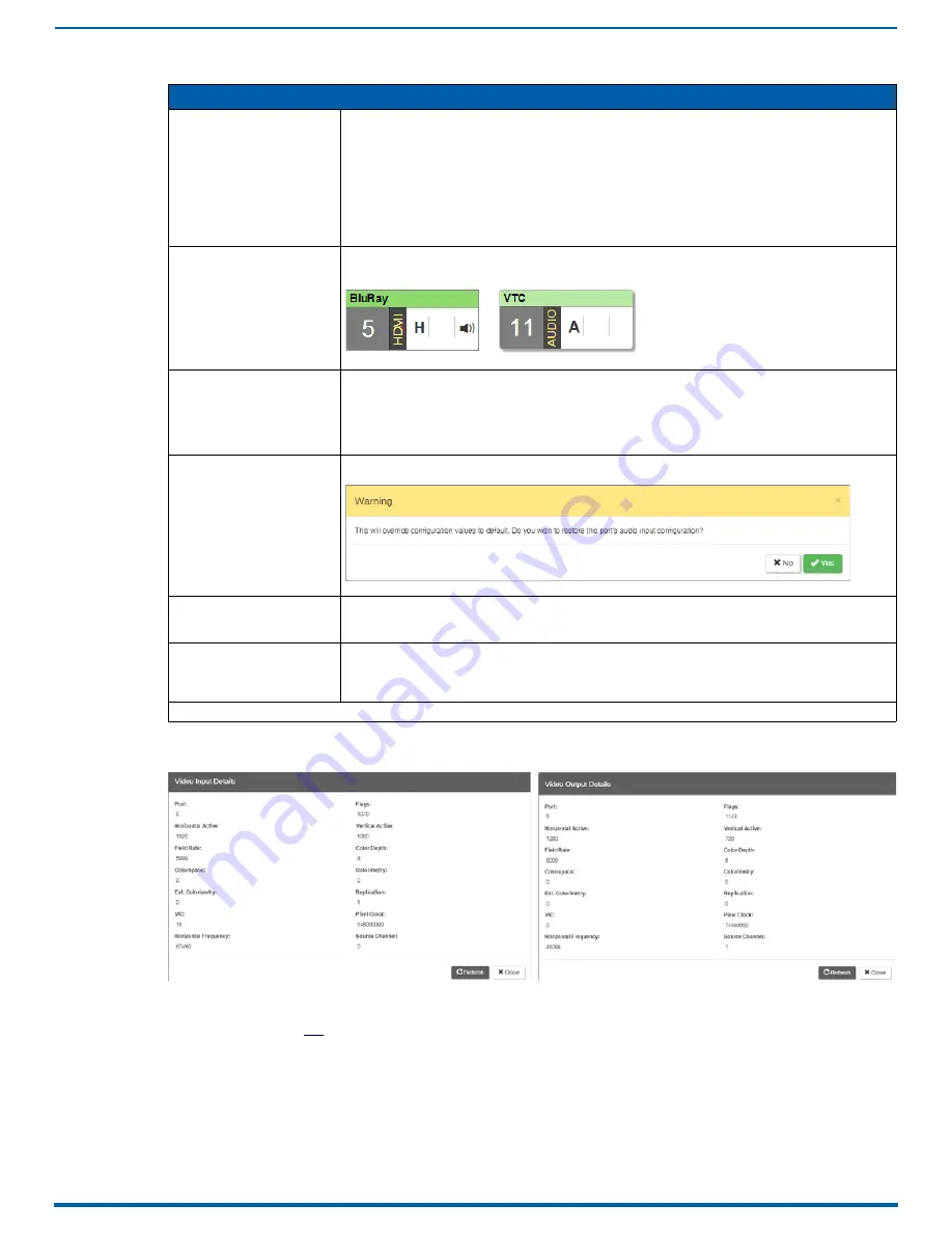
Restore to Default
(red) button
Click to open the Warning dialog, which requires you to select the Yes button to restore the currently
selected input or output to its factory default settings:
Video
Details
or
Audio Details
button
Click to display additional video or audio details for inputs or outputs, depending on current selection
(video: colorSpace, flags, pixelclock, etc.; audio: CTS Value, N Value, Audio Mute State, etc.).
Examples of both Video Input and Output Details are shown in FIG. 102. Audio details are similar.
Video
,
DXLink
, and
Audio
settings
The settings section of the Configuration page changes depending on the type of signal, whether it is an
input or an output, and whether a DXLink unit is attached. A variety of interface controls are used to
change the settings (e.g., buttons, sliders, drop-down lists) depending on the values involved.
Details for these settings follow this section.
Switcher Setup
button options are available on both the Switching and the Configuration pages.
FIG. 102
Video Input Details and Video Output Details Windows
Video button
Audio button


