

For warranty information, refer to www.amx.com.
08/2010
©2010 AMX. All rights reserved. AMX and the AMX logo are registered trademarks of AMX.
AMX reserves the right to alter specifications without notice at any time.
3000 RESEARCH DRIVE, RICHARDSON, TX 75082 • 800.222.0193 • fax 469.624.7153 • technical support 800.932.6993 • www.amx.com
93-46-861
REV:
F
Digital Audio I/O Boards – S/PDIF and TosLink
S/PDIF connectors are coaxial, and TosLink connectors are optical (remove the
protective caps from the TosLink jacks).
RGBHV+Stereo to CatPro I/O Boards – HD-15, 5-Term, and RJ-45
The outputs (RJ-45 connectors) on the Optima CatPro boards act as transmitters
(TXs) and
must
be used in conjunction with a CatPro RGBHV+Stereo Receiver (RX)
Module, FG1010-48-01, to complete the system. We recommend reading the system
setup information in the “Instruction Manual – Optima,” as well as the documentation
for the module. CatPro supports Cat5, Cat5e, Cat6, Cat6e, and STP cables.
Skew-free cable is
not
recommended for use with AMX AutoPatch equipment.
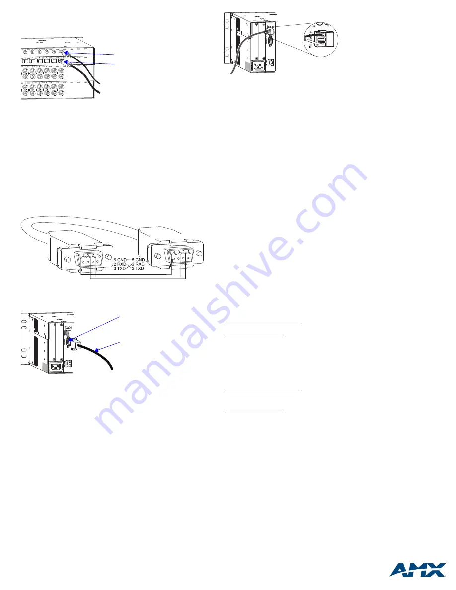
Establishing Serial Control
The Optima can be controlled by attaching an external control device/system to the
Control (RS-232 serial) port or to the Remote (XNNet) port, which uses AutoPatch
XNNet protocol for AMX AutoPatch devices.
Serial Control (PCs,
AMX Control Devices
, and third-party controllers)
Use the pinout in FIG. 7 when connecting a PC to the Optima Control port.
To establish external serial control:
1.
Plug the null modem RS-232 serial cable into the enclosure’s Control port.
2.
Plug the other end of cable into the serial port on the serial controller/device.
3.
Open serial communication software and set port settings to match the Optima
default settings (baud rate = 9600, data bits = 8, stop bit = 1, parity = none, and
flow control = none).
Establishing XNNet Control (SBCs, remote control panels, etc.)
XNNet connectors (labeled “Remote”) are on the CPU for 3 RU enclosures and are
available on an expansion board for 2 RU enclosures.
Communication Cable Requirements:
•
Two-conductor, 20 AWG, 7/28 strand cable with a drain wire or shield, such as
Alpha 2412C (customer supplied)
•
Maximum cable length: 1,000 ft. (305 m) total, including linked devices
On large control networks, termination may be required on the last linked device;
for termination information, see the device’s documentation.
To establish external XNNet control:
1.
Attach XNNet link cable to XNNet device according to the device’s instructions.
2.
Unplug the Remote connector on the Optima and loosen the screws.
3.
Insert the XNNet link cable wires according to FIG. 9 (either wire can be
inserted in either outside slot).
4.
Tighten the screws and plug in the Remote connector.
Applying Power
Important:
We recommend attaching all power cords to a surge protector and/or an
AC line conditioner.
To apply power:
1.
Attach power cord(s) and plug into power source (turn on power source if
necessary). The Power Indicator on the front of the enclosure illuminates.
2.
Apply power to any external devices (remote control panels, etc.) and then to
the source and destination devices.
Completing the Installation
Most Optima systems ship from the factory with an active switch (a switch that routes
the signal from Input 1 to all outputs for testing purposes). Before using the system
for normal operations, we suggest disconnecting all active switches and then
executing a test switch to verify that the system is working properly. If you do any test
switching using connections on an HDMI board, you may need to clear the board’s
sink key cache before completing the installation; see “Instruction Manual – Optima”
.
To complete the installation:
1.
Disconnect any active switches using one of the control options below.
2.
Execute a test switch that routes Input 1 to Output 2. (Component signals
require multiple connectors;
all
cables for that signal
must
be attached for the
test switch.)
3.
Attach the remaining source and destination devices.
Startup Control Options and Test Switch
Signals may only be routed from the inputs on a board to the outputs on the same
board because each board has its own switching matrix.
Control Panel (front or remote)
– The LCD on the panel illuminates and
displays the menu screen. For instructions on disconnecting any active switches and
executing a test switch, see the control panel’s “Quick Start Guide.”
AMX Control Devices
– The Optima is compatible with a number of AMX control
devices. For control programming information, see the instruction manual for the
specific interface.
APControl 3.0
– Install and open the program. Follow the setup wizard, which will
discover the system’s configuration information and open the APControl Launchbar.
To disconnect any active switches: From the Launchbar menu, select Views/
CrossBar and deselect all active crosspoints.
To execute the test switch: From the Launchbar menu, select Views/CrossBar and
click on the crosspoint for Input 1 / Output 2.
APWeb
– For APWeb expansion board information, see the “Instruction Manual –
Optima.” For APWeb Module installation, see the “Quick Start Guide – APWeb
Server Module.” For instructions on executing switches, see the “Instruction Manual
– APWeb
.”
Disconnect any active switches before executing a test switch.
BCS Commands
(HyperTerminal)
– When power is applied, a short splash screen
appears.
To disconnect any active switches: enter
DL0I#T
(where
#
is the input number) into
the terminal emulation program. When
DL0I#T
appears, the command is
successful.
To execute the test switch: enter
CL0I1O2T
into the terminal emulation program
(routes Input 1 to Output 2). When
CL0I1O2T
appears, the switch is successful.
Note:
These commands use Level 0, which is normally the default level. If the
commands do not work, check the
AutoPatch Connector Guide
to verify the level.
Additional Information Covered in “Instruction Manual – Optima”
See the “Instruction Manual – Optima” on the
AMX AutoPatch CD
or at
www.amx.com
for the following:
•
Creating local presets
•
Customizing channel names
•
Using APWeb or XNNet expansion boards
•
Adding or replacing I/O boards
•
Splash screen – system component information for diagnostic purposes
Reference Document for the Optima
The “Instruction Manual – BCS Protocol” is on the
AMX AutoPatch CD
and at
www.amx.com
. BCS (Basic Control Structure) is a programming language used for
programming control operations and for diagnostics purposes.
FIG. 6
Attach S/PDIF and TosLink connectors
FIG. 7
Pin diagram for DB-9 connectors on RS-232 serial cable
FIG. 8
Attach null modem RS-232 serial cable
C
C
C
C
Y
Y
Y
Y
Y
Y
C
C
C
C
C
C
Y
Y
Y
Y
Y
Y
C
C
S/PDIF connector
TosLink connector
PC: DB-9
AutoPatch: DB-9
Null modem RS-232 serial cable
Control (RS-232 serial) port
FIG. 9
Insert wires into Remote (XNNet) connector


