


Remote Workstation Graphics Card
Page 20
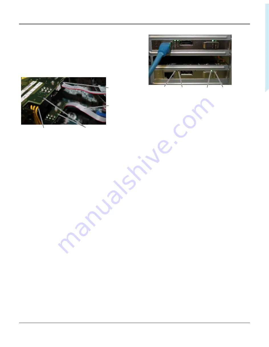
ACTIVITY
LED
INT FN
LED
STATUS
LED
SPEED
LED
Figure 13:
Check.the.status.LEDs
3.
Connect a zero client to the first DXP4.
Example:
Set the connection type to SLP and Host Discovery
and select the MAC address from the available list of hosts on
each zero client.
4.
Connect a zero client to the second DXP4.
4.6
Check the other Ethernet connection
1. Make sure that eight heads of video are present.
2.
Disconnect the Ethernet cable from the first DXP4 and
connect to the second DXP4.
When you swap the cable from the first DXP4 to the second
DXP4 the zero clients temporarily indicate a loss of signal and
then recover the connection.
The SPEED LED lights AMBER and ON, the ACTIVITY LED
flashes GREEN on the DXP4 connected to the Ethernet cable.
4.3 Install the second DXP4
1.
(For network solution B only) Connect the free end of the
interlink cable to the second DXP4.
2.
Connect the second PCIe power connector to the second
DXP4.
3. Install the second DXP4 into any free x8 or x16 PCIe slot in
the host PC.
PCIe power
connector
DXP4s
Interlink
cable
connector
Interlink
cable
Figure 12:
Connect.the.PCIe.and.Interlink.cables
4.
Make sure the DXP4 mounting bracket is fixed securely in the
PC.
4.4 Connect to the network
1.
For network solution A: connect an Ethernet cable to
one
of
the DXP4s.
2.
For network solution B: connect an Ethernet cable to
both
DXP4s.
4.5
Connect the zero clients to the host PC
1.
Connect the power cable to the PC
2.
Turn on the host PC and wait for both DXP4s to power up.
See
.
The STATUS and INT FN LEDs are GREEN and flash on both
DXP4s.
The ACTIVITY LED flashes GREEN to show network activity,
the SPEED LED is AMBER (or GREEN depending on link speed)
and ON on the DXP4 connected to the Ethernet cable.
The ACTIVITY and SPEED LEDs are OFF on the DXP4 with no
Ethernet cable.


