
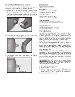


Installation of In-Line Turbulator
™
The In-Line Turbulator water circulation device is designed to
circulate the water stored in your diaphragm well tank.
1.
Inspect the In-Line Turbulator for any damage that may
have occurred during shipping. Insert the In-Line Turbulator
(Diagram 1) into the system connection of the expansion tank.
The Turbulator can only be inserted with the butt end out as
the locking tabs prevent it from being installed backwards.
2.
Palm press the In-Line Turbulator (Diagram 2) until the unit
locking tabs butt up against the system connection.
3.
Your diaphragm well tank is now ready to be installed
(Diagram 3).
Installation
System Connection
In-line Models:
WX-101 through WX-103: ¾" NPTM
WX-104 and WX-200: 1" NPTM
Vertical Stand Models:
WX-201 through WX-203: 1" NPTF
WX-205 through WX-350: 1¼" NPTF
Horizontal Models:
WX-102PS through WX-110PS: ¾" NPTM
WX-200PS, WX-202PS and WX-202H: 1" NPTM
Underground Models:
WX-200UG and WX-202UG: 1" NPTF
WX-250UG and WX-251UG: 1¼" NPTF
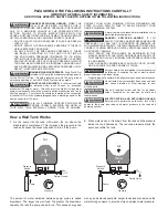
Pre Installation
The surface on which the Well-X-Trol is installed should be
capable of supporting its operating weight (including the weight
of water). The Well-X-Trol should be installed as close as
possible to the pressure switch. This will reduce the adverse
effects of added friction loss and differences in elevation
between Well-X-Trol and/or water supply main and switch.
Adjacent to pump:
This is the location chosen most often. The
Well-X-Trol tank can be used whether pumps are above or
below the surface. In either case, it protects the pump by
reducing surge, dampening pressure spikes, offering a point of
pressure control, and providing minimum run time. This location
also permits all equipment to be placed in an area that’s both
serviceable and secure.
At the end of long pipe runs:
The Well-X-Trol tank can be
positioned at the end of a long run of pipe so it can provide rapid
system response and adequate protection. When this location is
chosen, the pressure switch should either be relocated with the
Well-X-Trol tank or the setting should be adjusted to compensate
for any line pressure drop.
DO NOT LOCATE IN AN AREA WHERE
LEAKAGE OF THE TANK OR CONNECTIONS
COULD CAUSE PROPERTY DAMAGE TO THE AREA ADJACENT TO
THE APPLIANCE OR TO LOWER FLOORS.
1.
Remove protective air valve cap.
2.
Check pre-charge pressure.
3.
Release or add air as necessary to set the pre-charge
pressure 2 psig below the pressure switch pump cut-in
setting. (Example, 38 psig precharge for a 40/60 pressure.)
4.
Replace protective air valve cap.
Locking Tabs
Diagram 1.
Diagram 3.
Locking Tabs
Diagram 2.


