


335A-250-00
3
3/2019
Specifications Information and Repair Parts Manual
335 Series and 336 Series
x
Diaphragm Pumps
In some applications, it may be preferable to have suction/discharge
ports rotated 90 degrees to be in line with driver. If so, proceed as
follows:
a.
Remove four hex cap screws (Ref. No. A9), hex nut (Ref.
No. A13) and washers (Ref. Nos. A11 & A12) from pump
assembly to separate pump well (Ref. No. A3) from pump
base (Ref. No. A8).
b.
Rotate pump well 90 degrees clockwise so that driver is
positioned over top of discharge plate (Ref. No. W7).
c.
Be sure that pump well base and diaphragm (Ref. No. P17)
are aligned properly with one another. Then, reinstall four
hex cap screws, hex nuts and washer assemblies and
tighten.
GEAR BOX OIL
(Refer to Figure A,G)
3.
Place pump on a level surface. Fill pump gear box (Ref. No.
A1) with gear box oil before the pump is operated. Gear oil
must meet requirements of API GL-5 and military
specification MIL-L-2105B. Remove gear box housing fill
plug (Ref. No. G6). Remove level plug (Ref. No. G5). Pour
gear oil into gear box slowly until oil comes out of level plug.
Warranty on this unit is void unless the gear box is lubricated
with appropriate gear oil listed above. DO NOT OVER FILL!
INSTALLATION
NOTE:
In any installation where property damage can occur by pumps
not operating due to power outages, discharge line freezing or any
other reason, a backup system(s) and/or warning system(s) should be
used.
1.
Place the pump on a level, solid foundation, locating it as
close to the liquid as possible, making the suction line as
short and direct as possible.
2.
Install pipe nipples (Ref. No. A36) so the smoother side of
pipe end faces the suction and discharge hose.
Maximum discharge head is 25 feet or 10.9 psi. Operation over
this head or pressure will cause pump to stall and/or gearbox
damage. Use only rigid hoses.
3.
Attach suction piping to the suction inlet (Ref. No. W2) and
discharge piping to the discharge outlet (Ref. No. W7). The
suction line should be positioned such that there is a
continual upward slope from the fluid source to the pump.
Avoid using loops or sections of pipe or fittings, which might
permit air to become trapped.
NOTE:
If hose is used, be sure to use reinforced hose on both the
suction and discharge.
DO NOT USE
canvas or similar collapsible
materials.
NEVER USE PIPE REDUCER; PIPE SIZE MUST BE
EQUAL TO OR LARGER THAN PUMP PORT SIZE.
Suction line
must be airtight so that air cannot leak in and destroy priming vacuum.
On a permanent installation where piping is used, always connect a
piece of flexible hose between pump and piping so pump is free to
move slightly.
4.
It is advisable to use a strainer (Ref. No. W16) on the inlet
end of the suction hose or pipe. A properly sized strainer is
supplied with this unit and should be used at all times to
prevent damage. Keep the strainer clean. If possible,
suspend it to keep it from becoming clogged with muck,
roots, debris or leaves. It is best to keep hose free of kinks
as they will restrict flow and add excess loading to pump
and gearing.
5.
GASOLINE ENGINE UNITS:
Follow all instructions in the
engine manual before starting the engine. Fill engine with
oil, gasoline, etc.
AIR MOTOR UNITS:
Follow all instructions in the air motor
manual before starting unit.
ELECTRIC MOTOR UNITS:
It is strongly recommended
that this unit is plugged into a G.F.I. (Ground Fault
Interrupter) circuit. Consult your local electrician for
installation and availability.
6.
Input RPM (to pump)
– Input RPM must be between 1750
and 2750 RPM. Final pump speed will be 40 strokes/min.
with a 1750 RPM input and 60 strokes/min. with a 2750
RPM input.
Do not exceed 60 strokes per minute with the diaphragm pump.
OPERATION
Operate the diaphragm pump in an upright position only.
1.
This diaphragm pump is capable of priming "dry" up to
fifteen feet; it will prime much faster when it is filled with
clean water through priming cap (Ref. No. W6). Primed, it
can lift to 25 feet.
2.
Activate unit following engine or air motor manual or turning
unit on if electrical.
Do not control discharge capacity with a valve or similar device.
CLEARING JAM-UP
If large solids or an accumulation of sand or other sediment becomes
lodged in the pump well (Ref. No. A3) preventing the plunger arm
(Ref. No. A2) from making a full stroke, the pump should be
thoroughly cleaned as described in "If Pump Stalls" shown below.
Refer to parts list and illustration for parts identification.
If pump has stopped or stalled for any unknown reason, clean
out pump cavity thoroughly. Failure to comply with the "caution"
could result in damage to crank (Ref. No. P5/P9), plunger arm
(Ref. No. P1) or other parts of assembly.
1.
IF PUMP STALLS:
a.
Remove handle (Ref. No. A35).
b.
Remove four bolts (Ref. No. A9 & A10).
c.
Clean obstruction and all debris from pump well
(Ref. No. A3).
d.
Reassemble
pump
in
reverse
order
of
disassembly and return to service.
2.
IF PLUNGER ARM (Ref. No. P1) SEIZES AND GEAR BOX
OUTPUT SHAFT (Ref. No. G8) TURNS IN CRANK (Ref.
No. P5):
a.
Remove sheet metal guard (Ref. No. A4) by
loosening hand knob screws (Ref. No. A5).
b.
Disassemble pump and clean as described in
steps (a) through (d) listed for stalled engine jam
up.
c.
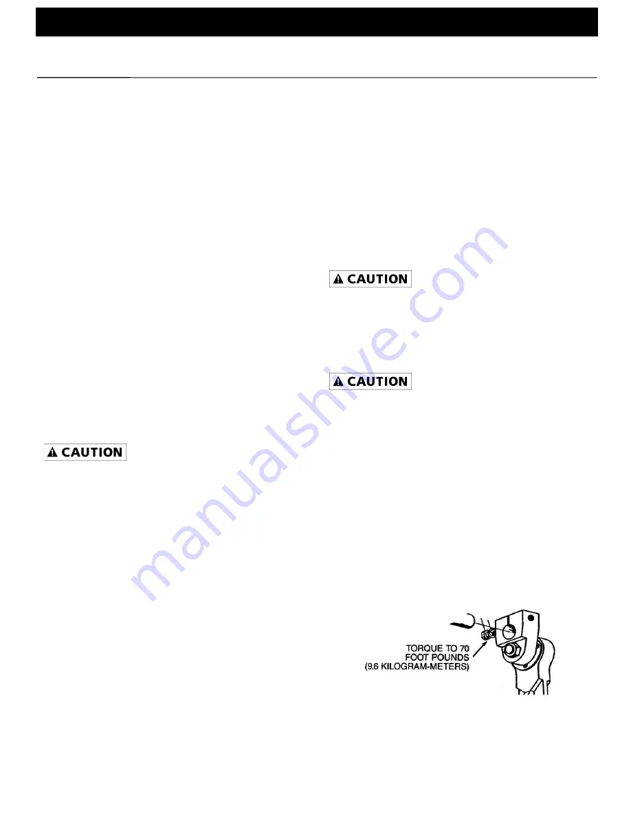
Torque the crank lock screw (Ref. No. P6) to 70
foot pounds with an appropriate torque wrench
(see Figure 3).
Figure 3
d.
Reassemble the pump in reverse order of
disassembly and return to service.