background image

AF408N User Guide

5

amscope.com

Setup

Attaching the Camera to a Microscope

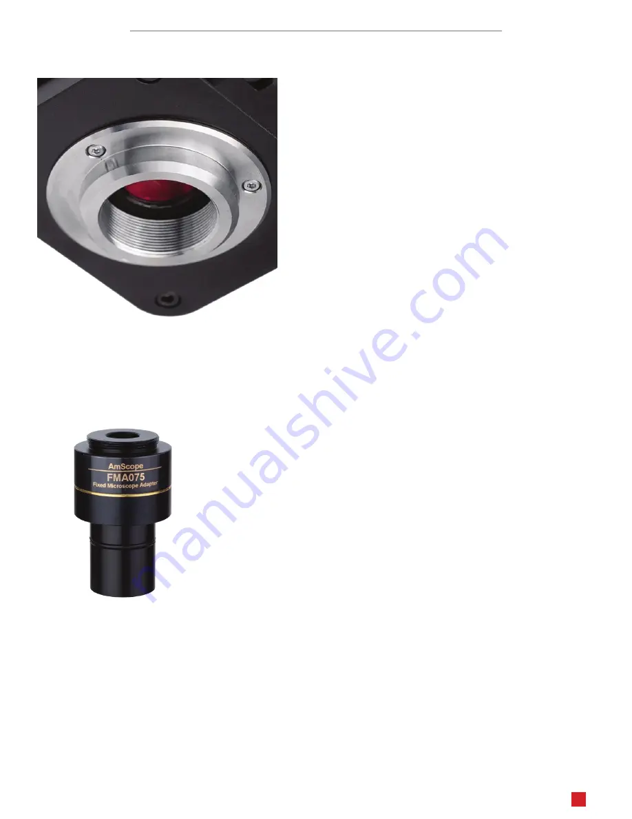
This camera uses a C-Mount standard lens mount. The camera can 

be mounted directly to a microscope which provides a C-Mount 

photo port, or it can be mounted to an ocular or photo port by 

using an optional compensating lens. The C-Mount standard uses a 

1” (25.4mm) diameter with 32TPI (0.794mm pitch).
Notice: Because this camera uses a mechanical focus drive which 

can move the image-sensor closer to the C-Mount interface, some 

older reduction lenses with extended threads may interfere with 

the motor’s range of motion. If the camera detects an obstruction, 

it will display a message on-screen.

To mount the camera to a C-Mount port, simply remove the camera’s lens-port dust-cap, then align the microscope’s 

port with the lens port. Rotate the camera in a clockwise manner until it is firmly attached. The photo port on some 

microscopes will have a rotating interface which can be locked and unlocked to change the orientation of the camera. If 

so, you can use this to properly align the camera to produce upright images. If not, you may need to unscrew the camera 

slightly to achieve the proper orientation.

To use a compensating lens, the correct lens must be used. A compatible compen

-

sating lens would have a C-Mount thread which would allow it to screw onto the 

camera’s lens mount. The other end would be cylindrical, and would slide into one 

of the microscope’s ocular ports or photo port. The compensating lens will have a 

magnification such as 0.5X or 0.37X. When the lens has a magnification below 1X, 

it is referred to as a reduction lens since it reduces the size of the image projected 

onto the camera’s sensor. The magnification should roughly match the optical for

-

mat of the camera’s image sensor (see Sensor Optical Format in the specification 

tables). For example, if the camera’s sensor format is 1/2”, then a 0.5X compensat

-

ing lens would be appropriate.

Attach the lens to the camera by aligning the threads with the camera’s lens port. Gently screw the lens into the port in 

a clockwise manner until it is firmly attached. Next, slide the lens into an appropriate port. Because of the camera’s size 

and weight, it is better to use a port on the microscope intended specifically for cameras, such as a vertical trinocular 

port. This will avoid tipping the microscope, and can prevent the camera from rotating. Additionally, a sizing adapter 

may be needed if the diameter of the lens’ tube does not match the diameter of the port. Some lenses will include sizing 

adapters such as a 23mm to 30mm adapter.

Summary of Contents for AF408N

Page 1: ...v0 9 20221115 AF408N 4K Auto Focus Multi Function Camera ...

Page 2: ... the instrument or injury to yourself or others Only use the provided power adapter or authorized replacement Incompatible power sources can cause damage to the instrument If you should lose the included power adapter please contact AmScope for information about a replacement Do not dismantle Dismantling can result in damage to the instrument and potential exposure to dangerous materials or electr...

Page 3: ...ork 8 WLAN 8 AP Mode 8 STA Mode 8 User Interface 9 The Virtual Keyboard 9 The Camera Control Panel 10 Image Exposure 11 Manual Exposure 11 Auto Exposure 11 Color 11 White Balance 11 The Measurement Toolbar 12 The Camera Control Toolbar 14 Overlay 15 Auto Focus 15 Settings 16 Network 16 Measurement 17 Magnification 18 Image Format 18 Video 19 Storage 19 Language 20 Miscellaneous 21 ...

Page 4: ...automatic manual Focus Drive Range 10 6mm to 5 4mm Video Resolutions 3840x2160 30fps File Formats JPEG TIFF photo MP4 video Recording Media Secure Digital up to 128GB optional USB flash drive I O HDMI video out USB 2 0 x 2 PC external media wi fi USB mouse SD Wi Fi Standard 802 11ac 2 4GHz 5GHz Lens Mount C Mount Power Requirements DC 12V 1A What s In The Box The AF408N standard outfits include On...

Page 5: ...ompensating lens the correct lens must be used A compatible compen sating lens would have a C Mount thread which would allow it to screw onto the camera s lens mount The other end would be cylindrical and would slide into one of the microscope s ocular ports or photo port The compensating lens will have a magnification such as 0 5X or 0 37X When the lens has a magnification below 1X it is referred...

Page 6: ... the camera by attaching its USB plug to the camera s USB port labeled USB Mouse Next connect the supplied power adapter by inserting its barrel connector to the camera s power port labeled DC 12V The power indicator located above the power port should be red which indi cates the camera is receiving power Press the camera s power button to initialize the camera The power indicator will change to b...

Page 7: ...elp file which can be accessed from the software s menu under Help The camera can be accessed from the computer using a USB connection or wi fi When the proper connection is made the camera will be displayed in the software s list of available devices Connecting with USB The camera can be connected to a computer using the provided USB cable The cable has a type A USB connector on either end Plug o...

Page 8: ...ed on the top left cor ner of the screen Move the cursor over the bottom of the screen to display the Camera Control Toolbar Click on the icon to open the Settings menu Select Network from the list then click on the WLAN tab The wi fi mode can be selected from a drop down selector AP Mode When AP mode is selected settings specific to this mode will be available The Frequency setting allows you to ...

Page 9: ...ngs are on the bottom By default the panels will only display when the mouse cursor is hovering over the appropriate area Left clicking on the pin icon will maintain the panel s visibility but will prevent other panels from opening The Virtual Keyboard If not using a hardware keyboard an on screen keyboard can be used to enter text or numeric values as needed Using the mouse s left button double c...

Page 10: ...ime but will result in increased noise levels Red Manually adjust the proportional Red level of the RGB video Green Manually adjust the proportional Green level of the RGB video Blue Manually adjust the proportional Blue level of the RGB video Auto White Bal ance Continuously adjusts RGB levels automatically based on the overall video content Manual White Balance Enables the manual RGB controls to...

Page 11: ...to the subject changes the amount of light collected will also change Auto exposure can continuously compensate for these changes This method assumes that the optimal amount of light would create an image with levels which would average to a middle tone Because of this images of light subjects may appear too dark and images of dark subjects may appear too bright For this reason adjustment can be d...

Page 12: ...ings for performing measurements Icon Function Pin the Measurement Toolbar Show Hide Measurement Objects Select Measurement Unit Select Magnification requires calibration process Object Selector Angle 4 Point Angle Point Arbitrary Angle Line 3 Point Lines Horizontal Line Vertical Line Parallel 3 Points Vertical Line Rectangle Ellipse 5 Point Ellipse Circle 3 Point Circle Annulus Concentric Circles...

Page 13: ... micrometer slide Export measurement information to CSV file Access the camera s settings Delete measurement object Exit measurement mode Left clicking on a measurement object will open the Object Location Properties Con trol Bar The icons on the control bar Move Up Move Down Move Left Move Right Adjust Color Delete When the Pin icon is clicked to lock the Measurement Toolbar the Camera Control Pa...

Page 14: ...oscope s optics or the camera s physical orientation Color Grayscale can be used to switch between the camera s normal color image and a desaturated image Freeze Video will pause the live video A Crosshair or Grid can be displayed to assist with segmenting and counting image alignment and other operations Overlay can be used to load a DXF file as a layer overlaying the on screen image The Auto Foc...

Page 15: ...otal range of motion which is displayed on the Auto Focus control panel 0mm represents a neutral position based on the standard flange focal distance for C Mount lenses 10 6mm represents the maximum distance the sensor can be moved away from the C Mount interface and 5 4mm represents movement toward the C Mount interface When Auto Focus is selected the focal point will be adjusted automatically an...

Page 16: ...ork LAN Camera models which include a wi fi dongle can be used with compati ble computers and mobile devices using a wireless local area network WLAN General Name The camera s name which will appear on the network Wi Fi AP Frequency Select the wi fi band 2 4GHz or 5GHz Channel Select the wi fi channel to use Password Edit the password other devices will use to connect to the camera STA SSID Passwo...

Page 17: ... Calibration Line Width Sets the width of lines used for calibration Color Sets the color of lines used for calibration Endpoint Sets the shape used at each endpoint of a line Includes null or rectangle Angle Point Line Parallel Line Vertical Line Rectangle Ellipse Circle Annulus Two Circles Arc Text Polygon Curve Scale Bar Arrow Each shape or element can be customized using attributes such as Lin...

Page 18: ...sed and additional information pertaining to the microscope or camera used Resolution The number of pixels per meter Clear All Clears all saved calibration data Delete Clears the selected calibration data Image Format Image Format settings allow you to determine whether measurement objects will be merged into saved images or em bedded as a separate layer Image Format Choose the file type to be use...

Page 19: ...ec with better compatibility across multimedia de vices but less efficient compression compared to H265 H265 Newer HEVC video codec with improved compression while retaining high quality Storage Storage displays the format of any recognized storage media including Secure Digital cards and USB flash drives If com patible media is recognized the media s file system will be shown such as FAT32 exFAT ...

Page 20: ...ser Guide 20 amscope com Language Language setting selects which language will be displayed Options include English Simplified Chinese Traditional Chinese Korean Thai French German Japanese Italian and Russian ...

Page 21: ...AF408N User Guide 21 amscope com Miscellaneous Miscellaneous settings include additional helpful settings ...

Page 22: ...ments Overlay Grids USB video output switch back to mouse operation ROI Color Select the color of the Region of Interest ROI frame Synchronized display as Camera Control Panel Cursor Size Auto Exposure Maximum expo sure time Set the maximum exposure time for the Auto Exposure mode Setting a lower number can improve the frame rate Auto Exposure Region Camera Parameters Import Import previously save...

Reviews: