background image

Chapter 2

Installing ReadySystem 1U Options

ReadySystem 1U

Users Guide

15

10. Insert eight M30.5, 6mm screws with washers into the standoffs on the enclosure floor.  See

Figure 2-8.

Connecting the Power Cables

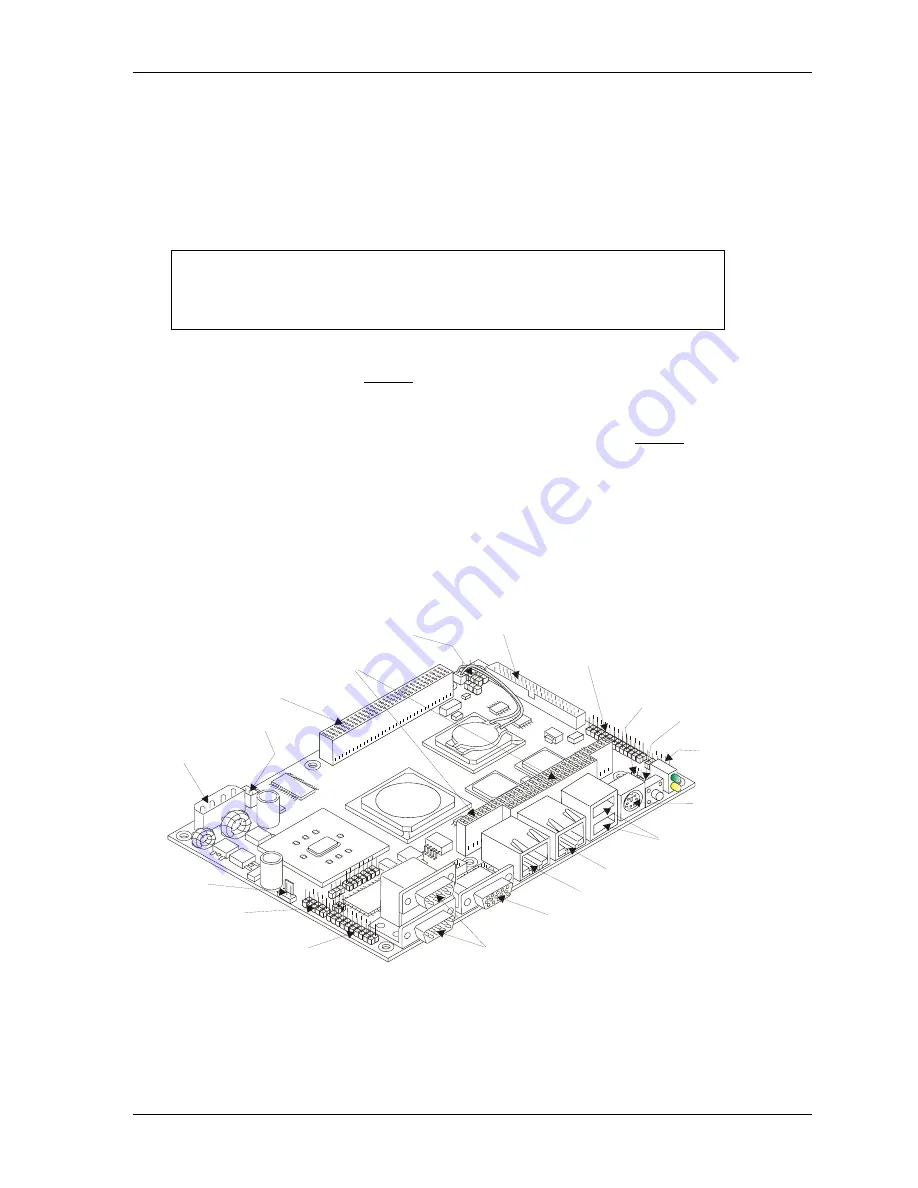
When connecting the cables, refer to the pin-1 designations shown in Figure 2-10.  Pin-1 is shown as a
black pin (round or square) at the connectors and jumpers, unless otherwise noted.  If you desire more
installation information than is provided in this guide refer to the ReadyBoard model QuickStart Guide
or Reference Manual.

NOTE

The connector reference designators in the text and illustrations are
based on the ReadyBoard 700 and may be different from your
respective ReadyBoard product, but the functions will be the same and
the connector locations will typically be in the same area.

1. Connect the Power Switch (two-wire) cable to the Utility connector (pins 1 & 2) on the

ReadyBoard, matching the red wire with pin-1.  See Figures 2-9, 2-10 and 2-11.

The Utility connector placement differs slightly on the various ReadyBoards, but all Utility
connectors use a 5-pin header and are in the general area shown in Figure 2-10.  Refer to the
respective ReadyBoard documentation for any variations, but match the red wire with pin-1.

2. Connect the Power In cable to the Power In connector (J4).  See Figures 2-9, 2-10 and 2-11.

The Power In connectors are located in the same place on all boards and use a 4-pin header.

3. Connect the Power-On cable to the Power-On connector (J6) on the ReadyBoard, as shown in

Figure 2-11.  See Figures 2-9 and 2-10.

The Power-On (3-pin) connector placement differs slightly on the various ReadyBoards.  Refer to
the respective ReadyBoard documentation for any variations.

4. Connect the DC In cable to the +5 volt Regulator board.  See Figure 2-11.


R

d

yS

y

1

U

_13a

PC/104-Plus (J12)

Power In (J4)

Power On (J6)

PC/104 (J13/14)

Primary IDE (J22)

Floppy/Parallel (J20)

USB 2 & 3 (J21)

Serial 3 & 4 (J3)
(COM 3 & 4)

Serial 1 & Serial 2 (COM 1 & 2)
(J5A/B)  (Serial 1 Lower) 

PS/2 Keyboard/
Mouse (J16)

 USB 0 & 1 (J15)
  (USB 0 Lower)

Ethernet 2 (J11)

Ethernet 1 (J10)

CRT (J8)

Audio In/Out (J19)
(hidden)

Utility (J18)
(hidden)

Infrared (J17)

GPIO (J2)

Fan (J1)

Figure 2-9.  Connector Locations (Typical ReadyBoard)

Summary of Contents for ReadySystem 1U

Page 1: ...ReadySystem 1U Users Guide P N 5001791A Revision B ...

Page 2: ...ication from time to time without obligation to notify any person of such revisions If errors are found please contact Ampro at the address listed below on the Notice page of this document TRADEMARKS Ampro and the Ampro logo are registered trademarks and CoreModule EnCore Little Board LittleBoard MightyBoard MiniModule ReadyBoard ReadyBox ReadyPanel and ReadySystem are trademarks of Ampro Computer...

Page 3: ...the ReadyBoard from Enclosure 10 Installing the ReadyBoard into Enclosure 12 Connecting the Power Cables 15 Connecting the Remaining Cables 17 Memory Installation 19 Tools Required 19 Installation Guidelines 19 Removing the SODIMM 19 Installing the SODIMM 21 Appendix A Technical Support 23 Appendix B System Overview 25 EPIC Architecture 25 Product Description 25 ReadyBox 1U Features 25 I O Panel D...

Page 4: ...Optional Rack Mount Hardware Installed 27 Figure B 3 I O Panel Controls and Connectors Front view 28 Figure B 4 I O Panel Access Openings Front view 29 Figure B 5 Width and Depth Dimensions Top view 31 Figure B 6 Width and Height Dimensions Front view 31 Figure B 7 Benchtop or Surface Mounting Dimensions Top View 32 Figure B 8 Benchtop or Surface Mounting Dimensions Front View 32 Figure B 9 Option...

Page 5: ...ystem 1U from the shipping container and inventorying the accessories Connecting peripherals to the ReadySystem 1U Powering up the ReadySystem 1U Information not provided in this Users Guide includes ReadyBoard model specifications Environmental requirements ReadyBoard model connector pin numbers and definitions Operating System programming or operating instructions NOTE Refer to the specific Ampr...

Page 6: ...s of the shipping box 2 Verify Contents Verify the contents of the shipping box against the Contents List included with your ReadySystem 1U shipping box If anything is missing or damaged call your sales representative Refer to Appendix A for contact information ReadySystem 1U Users Guide This document describes how to setup and power up the ReadySystem 1U and is provided on the ReadyBoard model Do...

Page 7: ...eadyBoard model and the hard drive with the desired OS pre installed form a complete system ready for operation Installing the Mounting Hardware 6 Connect the appropriate mounting hardware Connect the mounting hardware for surface mounting to the bottom or rear of the ReadySystem 1U See Figure 1 2 The four plastic feet are mounted prior to shipment and will protect the paint finish on the bottom o...

Page 8: ...ree Y cable connector with keyboard icon on it Connect the PS 2 mouse to the Y cable connector with the respective mouse icon Connect the CRT VGA monitor through its 15 pin cable to the CRT VGA connector on the I O Panel of the ReadySystem 1U See Figure 1 3 RdySy1U_03a LAN1 LAN2 Power LED IDE Activity LED Reset Switch Keyboard Mouse Compact Flash Slot Cover CRT VGA COM 1 COM 2 USB 0 USB 1 POWER HD...

Page 9: ...d model 10 pin RJ45 connector If not it uses the standard 8 pin RJ45 connector for 10 100BaseT Ethernet This connector is provided on the ReadyBoard This port is covered for single Ethernet ReadyBoard modules COM 1 COM 2 Serial 1 Serial 2 Use these two 9 pin DB9 serial ports for the standard RS232 connections to the ReadySystem 1U These two connectors are provided on the ReadyBoard AUDIO MIC Line ...

Page 10: ...ne shown below with the desired OS name displayed NOTE The 40 GB or greater hard disk drive 2 installed in the ReadySystem 1U enclosure comes with three partitions for the OS and swap space RdySy1U_4a GNU GRUB version 0 95 632k lower 250768 upper memory Fedora Core 2 6 9 xxx Use the and keys to select which entry is highlighted Press Enter to boot the selected OS e to edit the commands before boot...

Page 11: ... flash card before purchasing Not all card vendors define or support these parameters Consult the ReadyBoard product Hardware Release Notes and your compact flash card vendor for these parameter compatibilities Tools Required Use these tools to remove and install the compact flash card into or out of the ReadySystem 1U Small to medium Phillips screwdriver Anti static service kit Use a complete ant...

Page 12: ... necessary inspect the socket for bent pins or debris on the pins of the compact flash socket 6 Remove the compact flash card from its protective bag handling the compact flash card by its edges RdySy1U_05ab M3x0 5 Screws 2 Flat Head 3mm Compact Flash Protective Cover RFI Shield Figure 2 1 Removing Compact Flash Protective Cover CAUTION To prevent damage to the ReadyBoard or the compact flash card...

Page 13: ...re install the protective cover over the compact flash card See Figure 2 1 Reconnecting the protective cover will provide full EMI protection 10 Refer to the specific ReadyBoard documentation for any required jumper settings for the compact flash card before restoring power to the ReadySystem 1U CAUTION Depending on BIOS Setup some ReadyBoard products will power on as soon as you connect DC power ...

Page 14: ...emoved power turned off and the coaxial power cable disconnected skip to Step 5 If the ReadySystem has power applied and operating continue with the next step CAUTION To prevent damage to the ReadyBoard ensure the power switch on the ReadySystem is turned off and the coaxial power cable has been disconnected 2 Initiate a shut down sequence through the OS or hold in the power switch for 4 6 seconds...

Page 15: ...B 2 USB 3 to free the ReadyBoard from the enclosure because of the tight fit between the two USB connectors and the tops of the Ethernet ports If not you will have to remove the two USB connectors USB 2 USB 3 from the enclosure See Figure 2 4 6 If necessary remove the two USB cables USB 2 USB 3 connected to the enclosure I O Panel See Figure 2 4 RdySy1U_8ab Loosen or remove the USB2 and USB3 conne...

Page 16: ...cement RdySy1U_09ab M3x0 5 Screws 8 6 mm thread length with washers and lock washers ReadyBoard Note All standoffs have a thread size of M3x0 5 and accept M3x0 5 screws Figure 2 5 Removing ReadyBoard from Enclosure Installing the ReadyBoard into the Enclosure 1 Prepare the ReadySystem for ReadyBoard installation If the ReadySystem is already prepared for ReadyBoard installation with the top cover ...

Page 17: ...eadyBoard you need to do so before installing the ReadyBoard back into the enclosure If necessary for greater access to the internal space of the ReadySystem disconnect any cables between the 5 volt regulator and the internal parts of the ReadySystem See Figures 2 4 2 6 Refer also to the respective ReadyBoard QuickStart Guide for more cable removal information CAUTION To prevent damage to the stat...

Page 18: ...s on the I O Panel When you have the ReadyBoard in position you should clearly see the mounting holes for the eight standoffs under the board mounting holes and the LEDs should fit into the openings provided on the I O Panel RdySy1U_11a LAN Port Lip I O Panel ReadyBoard 10 Angle ReadyBox 1U Left Side View LAN1 I O Panel Insert ReadyBoard into enclosure just above standoffs ReadyBox 1U Right Side V...

Page 19: ... placement differs slightly on the various ReadyBoards but all Utility connectors use a 5 pin header and are in the general area shown in Figure 2 10 Refer to the respective ReadyBoard documentation for any variations but match the red wire with pin 1 2 Connect the Power In cable to the Power In connector J4 See Figures 2 9 2 10 and 2 11 The Power In connectors are located in the same place on all...

Page 20: ...Serial B J3 COM3 4 Serial B J3A B RS485 Termination JP6 COM3 4 CRT J8 VGA LCD Voltage Setting JP2 LVDS J7 Ethernet 2 J11 Ethernet 1 J10 USB 0 1 J15A B PS 2 Keyboard Mouse J16 PC 104 J13A B J14A B Lithium Battery B1 Utility J18 Audio In Out J19 USB 2 3 J21A B Floppy Parallel J20 CMOS Normal Clear JP3 IR Infrared J17 PC 104 Plus J12 Power On Header J6 Power In J4 GPIO J2 LCD J9 CF Master Slave JP4 F...

Page 21: ...n the I O panel as shown in Figure 2 12 The USB 2 cable is always connected to pins 3 5 on the 10 pin connector and USB 3 is always connected to pins 4 6 on the 10 pin connector regardless of the ReadyBoard model This 10 pin connector has odd even pin arrangement where all odd pins of the connector are on one side while all even pins are on the opposite side of the connector 2 Connect the USB2 USB...

Page 22: ...is typically located next to the jumper settings on the HDD See Figure 2 12 RdySy1U_16ab IDE Cable USB2 and USB3 Cable M3x0 5 Screws 4 Audio In Out Cable Figure 2 12 Installing IDE Audio and USB Cables 5 You may replace the top cover before restoring power to check the ReadySystem 1U operation or restore power to check system operation before replacing the top cover to the enclosure In either case...

Page 23: ... SODIMM Use this procedure to remove the SODIMM from the SODIMM socket on the ReadyBoard 1 Prepare the ReadySystem 1U for SODIMM removal If the ReadyBoard model is already prepared for SODIMM removal with the ReadyBoard removed from the enclosure skip to Step 7 If the ReadySystem has power applied and operating continue with the next step CAUTION To prevent damage to the ReadyBoard ensure the powe...

Page 24: ...o discharge any static electricity 8 Locate the SODIMM socket DIMM1 on the bottom of the ReadyBoard model See Figure 2 13 9 Open both retaining latches to release the SODIMM from the socket See Figure 2 13 The SODIMM will spring up to a 45 angle once you open both retaining latches If the SODIMM does not spring up to a 45 angle then the retaining latches have not released the SODIMM from the socke...

Page 25: ...wrist ankle strap and a grounding mat connected to ground Leave the SODIMM in the anti static bag until you are ready to install it Before you remove a SODIMM from the anti static bag touch a grounded unpainted metal surface to discharge any static electricity 3 Disconnect the coaxial power cable from the DC IN connector 4 Remove the six screws holding the top cover to the ReadySystem enclosure an...

Page 26: ...counter any resistance you may not have inserted the SODIMM far enough into the socket 13 If the retaining latches do not close completely on the SODIMM remove it and repeat Steps 10 to 12 14 Reinstall the ReadyBoard model into the ReadySystem 1U enclosure Refer to the Installing the ReadyBoard procedure for more information 15 Reconnect the cables to the ReadyBoard model Refer to Connecting the C...

Page 27: ...ssistance by going to the Ask a Question area in the Virtual Technician Requests can be submitted 24 hours a day 7 days a week You will receive immediate confirmation that your request has been entered Once you have submitted your request you must log in to go to the My Stuff area where you can check status update your request and access other features Embedded Design Resource Center This service ...

Page 28: ...Appendix A Technical Support 24 Users Guide ReadySystem 1U ...

Page 29: ...omputing solutions can be designed into even more space constrained environments than ever before The EPIC standard boasts the same highly flexible and adaptable system expansion as EBX easily allowing addition of modular functions such as USB 2 0 IEEE 1394 Firewire or wireless networking not usually contained in standard product offerings The EPIC standard also brings stability to the mid sized e...

Page 30: ...CE approval depends on the exact system assembled Power AC to DC power adapter optional Power On Off switch DC power screw type coaxial input connector RdyBx1U_01a Momentary Power Switch Connector Indicator Openings for ReadyBoard Compact Flash Card Cover and Opening DC Power In Connector ReadyBox 1U I O Panel ReadyBox 1U Top Cover Connectors with Internal Cables for ReadyBoard Headers Figure B 1 ...

Page 31: ...tility connector DC IN This 2 pin coaxial connector is connected to the internal DC regulator and accepts 12 or 24 VDC 5 from an AC to DC converter brick power supply Audio MIC Line In Line Out These two 3 pin connectors and one 2 pin connector MIC with respective cable are provided with the ReadyBox 2U The integrator must connect the cable to the Audio In Out connector on the ReadyBoard USB 2 3 T...

Page 32: ...his reset switch is provided on the ReadyBoard Pressing the Reset switch supplies a ground signal on the reset line causing a hard reset Keyboard Mouse This 6 pin single PS 2 Keyboard Mouse connector is provided on the ReadyBoard It requires a dual PS 2 output cable provided in the ReadyBoard SBC QuickStart kit USB 0 1 These two 4 pin USB type A connectors are provided on the ReadyBoard LAN 1 Ethe...

Page 33: ...ctivity LED Compact Flash Socket Typical ReadyBoard Side view Figure B 4 I O Panel Access Openings Front view Power IDE LED Definitions Table B 3 provides the LED colors and definitions for the Power and IDE drive activity LEDs that are part of the installed ReadyBoard and Figure B 3 shows the locations Refer to the specific ReadyBoard SBC for the Ethernet LED activity Table B 3 Power IDE Activity...

Page 34: ... humidity non condensing Power Specifications Table B 5 lists the power requirements for the ReadyBox 1U Table B 5 Power Requirement Parameter Description Input Type 12VDC 5 or 24VDC 5 Physical Specifications Table B 6 gives the physical dimensions of the ReadyBox 1U as shown in Figures B 5 and B 6 and the mounting dimensions in Figures B 7 through B 12 Table B 6 Weight and Footprint Dimensions Pa...

Page 35: ... B 5 through B 10 show the ReadyBox 1U enclosure dimensions and mounting dimensions 186mm 7 32 8 00 203 2mm 180mm 7 09 Top View 8 244 209 4mm Figure B 5 Width and Depth Dimensions Top view RdyBx1U_07a 1 73 44mm 180mm 7 09 I O Panel Front View Figure B 6 Width and Height Dimensions Front view ...

Page 36: ...ew 158mm 6 22 216mm 8 50 186mm 7 32 180mm 7 09 8 24 209 4mm 2 13 54mm 70 0mm 2 76 90mm 3 54 115mm 4 53 1 4 20 UNC 4 0 38 9 8mm 0 15 3 9mm RdyBx1U_08a Figure B 7 Benchtop or Surface Mounting Dimensions Top View RdyBx2U_09a 0 28 2 02 7 2mm 51 2mm 216mm 196mm 8 50 7 72 I O Panel Front View Benchtop or Surface Mounting 1 73 44mm 180mm 7 09 Figure B 8 Benchtop or Surface Mounting Dimensions Front View ...

Page 37: ... 8 68 17 07 481 8mm 18 97 153 6mm 204 4mm 27mm 8 00 203 2mm Top Cover View Figure B 9 Optional Rack Mounting Dimensions Top View 180mm 469mm 461mm 481 8mm 7 09 18 46 18 15 18 97 1 25 1 73 31 75mm 44mm I O Panel Front View 0 225 5 8mm RdyBx1U_13a Figure B 10 Optional Rack Mounting Dimensions Front View ...

Page 38: ... of the top cover location The four optional plastic feet with screws are also shown in Figure B 12 RdyBx1U_02ba 1 4 20 UNC Screws 6 Rackmount Sides 2 Left Right Figure B 11 Rack Mounting Hardware RdyBx1U_14ab Remove Top Cover M3x0 5 Screws 6 Figure B 12 Removing Top Cover NOTE Slide the top cover to the rear as shown in Figure B 12 before lifting the top cover off the enclosure ...

Page 39: ......

Page 40: ......

Reviews: