


Chapter 1
ReadyPanel Setup
ReadyPanel
User’s Guide
5
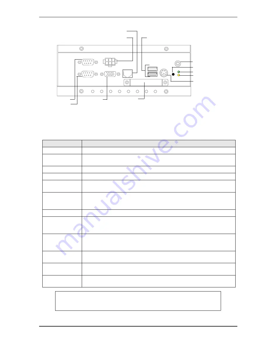
Figure 1-3. Flat View of ReadyPanel I/O Panel
Table 1-2. I/O Panel Connectors, Controls, and Indicators
Control/Connector
Description
DC Power In
This 6-pin connector accepts input from the external DC In cable adapter.
VGA
Use this standard 15-pin (DB15) connector for the video connection. This connector
resides on the ReadyBoard.
Mouse/Keyboard
This 6-pin single PS/2 mouse and keyboard connector resides on the ReadyBoard.
USB 0 & 1
These standard USB connectors reside on the ReadyBoard.
LAN 1 (Ethernet 1)
This 8-pin (RJ45) Ethernet port is used for the 10/100BaseT Ethernet connection and
resides on the ReadyBoard.
COM 1& COM 2
(Serial 1 & Serial
2)
Use these two this 9-pin (DB9) serial ports for the standard RS232 connections to the
ReadyPanel. These connectors reside on the ReadyBoard.
AUDIO: Line Out
Use this audio out connector for standard stereo out connection from the ReadyPanel.
Power LED
This green power-on indicator, shown in
Figure 2-1 on page 10
, resides on the
ReadyBoard and glows when power is turned on and goes dark when the ReadyPanel
power is turned off.
Storage Activity
LED
This yellow activity indicator, shown in
Figure 2-1 on page 10
, resides on the
ReadyBoard and flickers when IDE or compact flash card activity occurs in the
ReadyPanel.
Reset Button
Press this reset button, momentarily, to reset the ReadyPanel (hard reset). This button
resides on the ReadyBoard.
Compact Flash
Cover and Slot
This compact flash cover and slot (not shown) protects the compact flash card if
installed, and ensures good EMI shielding for the ReadyPanel.
Compact Flash
Socket (not shown)
The compact flash socket is provided on the underside of the ReadyBoard and
accepts the compact flash card through the compact flash slot.
NOTE
If you wish to connect a Hard Disk Drive (HDD) Floppy Disk
Drive (FDD) or CD-ROM to the ReadyPanel, you can use one of
the USB ports to connect the device.
USB 0 (top), USB 1 (bottom)
Compact Flash
VGA
10/100 Ethernet (LAN 1)
Mouse/Keyboard
Power LED
Reset Button
Serial 1 (COM1)
Serial 2 (COM2)
Storage Activity LED
Audio Line Out
DC Power In
Summary of Contents for P/N 5001795A REV A
Page 1: ...ReadyPanelTM 6 5 User s Guide P N 5001795A Rev A...
Page 4: ...Contents iv User s Guide ReadyPanel...
Page 12: ...Chapter 1 ReadyPanel Setup 8 User s Guide ReadyPanel...
Page 18: ...Chapter 2 ReadyPanel Components 14 User s Guide ReadyPanel...
Page 20: ...Appendix A Technical Support 16 User s Guide ReadyPanel...


