

14
Temposonics
®
GB-Series SSI
Operation Manual
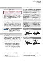
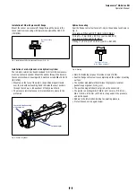
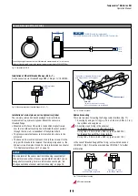
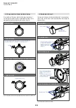
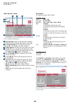
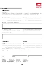
4.6 Replacement of base unit
The base unit of the sensor models GB-M and GB-T is replaceable as
shown in Fig. 19. The sensor can be replaced without interrupting the
hydraulic circuit.
Base unit (GB-B)
Sensor electronics housing
Plastic tube with
inner sensor element
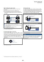
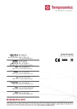
1. Loosen the screws.
You do not need to loosen the screws
(3 screws DIN 915 M4x6 A2)
completely. Normally it is
sufficient if you turn the
screws 4 ×.
A/F 2
2. Pull out the base unit.
There is an O-ring inside the
flange of the GB-M and GB-T
sensor.
Position the O-ring as shown in
the figure before inserting the
new base unit (GB-B).
O-ring
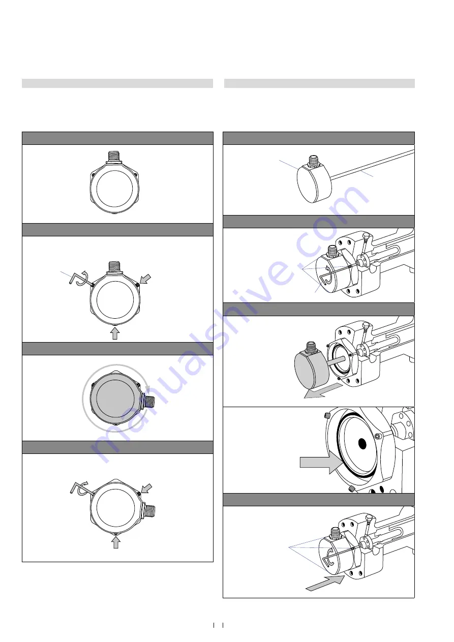
3. Insert the new base unit. Tighten the screws.
Fastening torque: 1.6 Nm
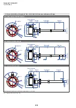
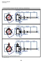
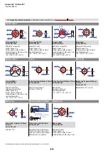
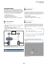
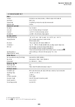
4.5 Change orientation of sensor electronics housing
The orientation of the sensor electronics housing respectively of
the electrical connection of sensor models GB-M and GB-T can be
changed after mounting. Follow the instructions in Fig. 18.
Fig. 18: Align sensor electronics housing respectively electrical connection of GB-M / GB-T
Fig. 19:
Replacement of the base unit (GB-B)
GB-M / GB-T sensor
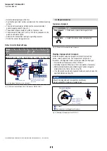
1. Loosen the screws.
You do not need to loosen the screws (3 screws DIN 915 M4x6 A2)
completely. Normally it is sufficient if you turn the screws 3 ×.
A/F 2
2. Turn the sensor electronics housing to the desired orientation.
360°
3. Tighten the screws.
Fastening torque: 1.6 Nm