background image


Amphenol Network Solutions 

All rights reserved. 12.18.19 139688-3 

509.926.6000 – amphenol-ns.com 

100A Dual-Feed 

Breaker Panel


30. Re-install covers over output and alarm terminals.  

This procedure is complete.  


1.4 Replacing Output Circuit Breakers


ALERT! Although difficult to remove from the panel, circuit breakers can be disconnected  

and replaced.  

Procedure steps:  

You can replace any installed circuit breaker value from 1A to 15A with another circuit breaker value, 

regardless of the original size. The 20A circuit breakers can only be replaced by 20A circuit breakers or 

smaller. Replacing a smaller circuit breaker with a 20A can result in damage to the fuse panel.  

1.  Place the breaker to be replaced in the off position.  

2.  Using a very small, flat-tipped screwdriver, carefully pry out on the bottom of the breaker while 

applying upward force on the face of the breaker.  


This should raise the bottom of the breaker so it slightly protrudes out of the front of the panel.  

3.  While preventing the breaker from going back into the panel, depress the bottom tab with the 

screwdriver and pull out on the breaker.  


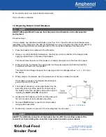
This starts the tab through the panel front opening so that it is dislodged about 

1

/

16 

in. (~.15 cm) at  

the bottom.  

4.  While pulling on the breaker, work the screwdriver at the top to release the top tab.  


If both tabs are released, the breaker should begin to 

pull out the front of the panel.  

5.  The breaker conductors can be pulled loose from the 

assembly at the rear of the panel. Do not pull out on 

the breaker more than necessary when removing and  

installing the 

LOAD

 and 

LINE

 connectors.  

6.  Gently work the breaker out the front of the panel until 

the rear connectors can be accessed by pliers.  

7.  Remove 

LOAD

 (bottom) connector from the breaker 

using needle-nose pliers.  

8.  Restrain the connector to prevent it from traveling back into the panel.  


ALERT! The LINE side connection of the breaker has live VDC. Do not allow contact of the 

connector (or tools holding the connector) to grounded ironwork or panel chassis.  


Figure 9 – Tab Release 

Summary of Contents for T009-5030 Series

Page 1: ...100A Dual Feed Breaker Panel T009 5030XXXXXXX Installation Guide...

Page 2: ...data and communications markets We design manufacture and distribute products for customers who need an end to end solution for network connectivity fiber power distribution and rack management We co...

Page 3: ...mary 11 1 6 1 Normal Operation 11 1 6 2 Input Power Failure 11 1 6 3 Output Breaker Opens either being tripped or manually turned off 11 1 7 Schematic Drawing 12 1 8 Assembly Drawing 13 List of Figure...

Page 4: ...ccessories Page 10 for ordering optional and replaceable items output breakers face plates lugs ETSI mounting kit and more Mechanical Specifications Dimensions nominal without brackets Width Height De...

Page 5: ...vice rating 125A Maximum continuous load rating total 100A per feed Maximum output interruption device rating 20A per circuit breaker Maximum continuous output load rating 16A per circuit breaker Alar...

Page 6: ...tion If you need assistance call Amphenol Network Solutions Technical Support at 509 926 6000 or email us at getinfo amphenol ns com Inspect equipment after unpacking and compare it to the packing lis...

Page 7: ...unused rack position and mount panel using the four screws and lockwashers provided as shown in Figure 3 It s best to mount the panel as high as possible on the rack Tighten screws to 35 in lb 4 29 N...

Page 8: ...to the panel is turned off 6 Make sure the input power is off 7 For input wiring wiring used as inputs to this distribution panel proceed as follows a Crimp dual hole compression lugs onto suitable co...

Page 9: ...ress and hold ALARM RESET on front of panel for 5 seconds to verify that all LEDs are in working order 14 With one or all circuit breakers off test fuse alarm relay contacts at FUSE ALARM terminals on...

Page 10: ...nation labels supplied to record outputs as specified by operating company standard installation procedures 23 Make sure inputs at loads are disabled by removing all power cards or all input fuses at...

Page 11: ...so it slightly protrudes out of the front of the panel 3 While preventing the breaker from going back into the panel depress the bottom tab with the screwdriver and pull out on the breaker This starts...

Page 12: ...eaker and check the orientation of the new breaker 12 Press the spade connector of the new breaker into the pliers held LINE connector until it is fully seated Visually inspect the connection to be su...

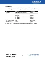
Page 13: ...Amphenol Network Solutions Part No 117995 included with your panel Item Description Part Number Alarm Card Power CB LEDs with Alarm Reset 400329 Circuit Breaker1 1A long delay 129316RC 3A long delay...

Page 14: ...osed b C to NO is open 4 POWER FAIL relay is energized so that a C to NC is closed b C to NO is open 1 6 2 Input Power Failure 1 POWER ON A or POWER ON B LED s will go off 2 POWER FAIL relay de energi...

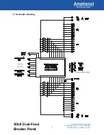
Page 15: ...12 Amphenol Network Solutions All rights reserved 12 18 19 139688 3 509 926 6000 amphenol ns com 100A Dual Feed Breaker Panel 1 7 Schematic Drawing Shown in alarm state Not Used Not Used...

Page 16: ...lutions convey any license under its patent rights or the patent rights of others This document and the products described herein are subject to change without notice 1 70 1 25 23 00 58 4 22 31 56 7 1...

Reviews: