background image


C2X 

Amphenol Telect 

All rights reserved. 07.10.18 149825 A0 

1-509-926-6000 

1.1.3 C2X 

– 2RU 

Dimensions 

3.5" H x 18.98" W x 13.75"; depth is 18.50" when front fiber management bezel is added  

Optical specifications 

Split Ratio (dB) 

(net/mon) 

50/50 

60/40 

70/30 

80/20 

90/10 

LC Multimode 

3.9/3.9 

2.9/4.9 

2.2/6.15 

1.65/7.95 

— 

LC Single mode 

3.7/3.7 

2.8/2.8 

2.0/6.1 

1.35/8.05 

0.85/12.05 

MPO Multimode (SR4) 

4.3/4.3 

— 

2.4/6.4 

— 

— 

Chassis density  

19": 2RU 

– 8 trays – 8 dual AOMs – 96 SC connectors – 192 LC connectors  

Access 

Front and rear 

Mounting options 

Standard 19" rack  
23" rack available with optional extension brackets  


1.1.4 C2X 

– 1RU 

Dimensions 

1.75" H x 18.98" W x 13.75"; depth is 18.50" when front fiber management bezel is added  

Optical specifications 

Split Ratio (dB) 

(net/mon) 

50/50 

60/40 

70/30 

80/20 

90/10 

LC Multimode 

3.9/3.9 

2.9/4.9 

2.2/6.15 

1.65/7.95 

— 

LC Single mode 

3.7/3.7 

2.8/2.8 

2.0/6.1 

1.35/8.05 

0.85/12.05 

MPO Multimode (SR4) 

4.3/4.3 

— 

2.4/6.4 

— 

— 

Chassis density  

19": 1RU 

– 4 trays – 4 dual AOMs – 48 SC connectors – 96 LC connectors  

Access 

Front and rear 

Mounting options 

Standard 19" rack  
23" rack available with optional extension brackets  


Summary of Contents for C2X

Page 1: ...C2X Fiber Distribution Panel Installation Guide...

Page 2: ...t notice Connecting the future for over 30 years Amphenol Telect looks beyond what s possible in network connectivity and power management We design and manufacture products that link fiber optic netw...

Page 3: ...Patch Plates 11 2 2 5 Splice Tray 12 2 2 6 Front Cable Management Bezel 12 Section Three Installation Considerations 13 3 1 Unpacking 13 3 1 1 Chassis Contents 13 3 1 2 Module Configurations 13 3 2 In...

Page 4: ...nstalling Patch Plates into the Chassis 22 7 2 Removing Patch Plates from the Chassis 23 Section Eight C2X Port Labeling and Designation 24 8 1 Port Labeling 24 8 2 Designation Cards 24 Section Nine R...

Page 5: ...in a rack 17 Fig 4 7 Mounting the 1RU C2X chassis 18 Fig 5 1 Inserting a module into a tray 19 Fig 5 2 Removing modules from the tray 19 Fig 6 1 Installing trays in the chassis 20 Fig 6 2 Removing tr...

Page 6: ...2 8 2 0 6 1 1 35 8 05 0 85 12 05 MPO Multimode SR4 4 3 4 3 2 4 6 4 Chassis density 19 4RU 16 trays 16 dual AOMs 216 SC connectors 432 LC connectors Access Front and rear Mounting options Standard 19...

Page 7: ...C connectors 192 LC connectors Access Front and rear Mounting options Standard 19 rack 23 rack available with optional extension brackets 1 1 4 C2X 1RU Dimensions 1 75 H x 18 98 W x 13 75 depth is 18...

Page 8: ...tructions to which the user should adhere CAUTION Indicates a hazardous situation which could result in minor or moderate injury WARNING Indicates a potentially hazardous situation which could result...

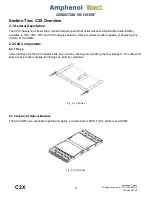
Page 9: ...nd 4RU chassis solutions C2X is modular solution capable of deploying any mixture of C2 AOMs 2 2 C2X Components 2 2 1 Trays Universal trays for the C2X chassis slide in and out by locking and unlockin...

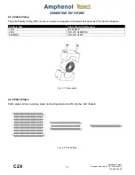
Page 10: ...2X chassis are available to install the C2X chassis in a 23 rack All extension brackets are sold separately See table below for sizes and part numbers Bracket Size Part Number 1RU 144049 2RU 144051 3R...
Page 11: ...ble IFC clamp is a cable management clamp kit that secures IFC onto the chassis Chassis Size Cable Clamp Part Number 1RU NO CLAMP 2RU C2X KIT CLMP2RU 3RU 4RU C2X KIT CLMP 2 2 5 Patch Plates Patch plat...

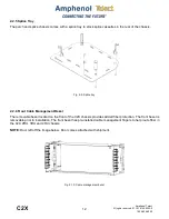
Page 12: ...Front Cable Management Bezel The removable bezel located on the front of the C2X chassis provides added fiber protection The front bezel is removable prior to installation The front bezel has pre ins...

Page 13: ...ns of security and be controlled by the authority responsible for the location ALERT Prior to chassis installation ensure there is enough space in front and rear to access cabling ALERT Only use compo...

Page 14: ...ambient temperature of the rack environment may be greater than room ambient Consider installing the equipment in an environment compatible with the maximum ambient temperature Tma specified by the ma...

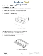
Page 15: ...ns on the left and right side of the front door 2 Pull the locking pins out of the locked position to release the door 3 Pivot door down on the hinges to open The following installation instructions r...

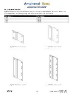
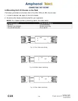
Page 16: ...he desired rack space for the C2X chassis 2 Determine the chassis positioning that fits your application NOTE The chassis has three positioning options See table below Connector Length Chassis Positio...

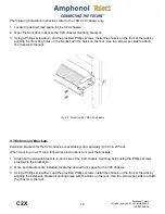
Page 17: ...assis mounting brackets 4 Using a Phillips screwdriver with 6 extension and the provided Phillips screws install the chassis on the front of the rack by aligning the mounting holes on the bracket with...

Page 18: ...to the rack 4 3 Extension Brackets Extension brackets for the C2X chassis are available sold separately to fit in a 23 rack When mounting to a 23 rack follow these instructions to mount the brackets 1...
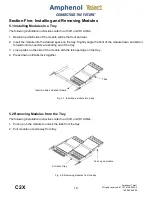
Page 19: ...the front of the module down and slide it forward until connectors are sticking out of the tray 3 Line up tabs on the side of the module with the tab openings on the tray 4 Press down until tabs lock...

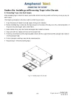
Page 20: ...ss space for trays and modules 2 Before installing trays make sure the tray plungers on the sides of the tray are in the unlocked position If they are not pull plungers out to unlock them 3 Slide bott...

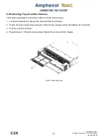
Page 21: ...ion instructions refer to all C2X chassis sizes 1 Locate the desired tray that will be removed from the chassis 2 Unlock the tray plungers by pulling out until you hear plungers snap and release from...

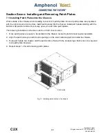
Page 22: ...bottom most position and work your way up as you add more patch plates The following installation instructions refer to all C2X chassis sizes 1 Once patch plates are ready to be installed in the chass...

Page 23: ...er to all C2X chassis sizes 1 Locate the desired patch plate that will be removed from the chassis 2 Unlock the locking pins by pulling pins out until you hear pins snap and release from the chassis 3...

Page 24: ...cards are used to identify adapter fiber jumper information at the front and rear of the chassis Designation cards for the 4RU 3RU and 2RU are designed specifically for each chassis size The followin...

Page 25: ...or to the front or rear of the C2X 1RU chassis 2 Attach Velcro patches onto the designation cards as well as front and rear of chassis Place patches and designation cards in locations shown in Fig 8 2...

Page 26: ...o route fiber The following installation instructions refer to the C2X 4RU 3RU and 2RU chassis sizes 1 With patch plates or trays already installed in the chassis route fiber into and through the cabl...

Page 27: ...atch plate 1 With patch plates or trays already installed in the chassis route fiber into the cable management openings Fiber cables can be routed all to the left all to the right or split with one si...

Page 28: ...the end of the Velcro band b Tighten the band to the slot c Repeat the process at the opposite side attaching the Velcro band to the splice tray s tie down slot 2 Place the first splice cassette in th...

Page 29: ...of the cassette 3 Insert IFC cable into IFC holder leaving a minimum of 12 maximum 1 meter of 250 m fiber to be routed counter clockwise from the insertion point 4 Leave approximately 1 of Kevlar out...

Page 30: ...nufacturer instructions c After splicing inspect splice for flaws If needed cut and resplice before heat shrinking protective sleeve over the completed splice d Place spliced fiber into splice holder...

Page 31: ...31 C2X Amphenol Telect All rights reserved 07 10 18 149825 A0 1 509 926 6000 3 Coil the spliced fibers back into the splice cassette Fig 11 4 Coiling fiber into cassette...

Page 32: ...agement fingers and adjust fibers as necessary to maintain proper bend radius 5 Re install the clear cover on the cassette NOTE To install the completed splice module into the chassis refer to Section...

Page 33: ...3RU Chassis 1 Measure the diameter of the incoming IFC cable 2 If needed remove and discard leaves from the center of the cable clamp until the correct dimensions the diameter of the IFC is obtained 3...

Page 34: ...cable and cable clamp to the cable clamp bracket using the two 2 7 x 50 mm screws washers and nuts NOTE Loosely tighten clamp to IFC to allow for adjusting length of cable 5 Attach the cable clamp bra...

Reviews: