background image

Page 4 

November 2011 

Maintenance 

Ampco Pumps Company 

Pump Assembly


4)   

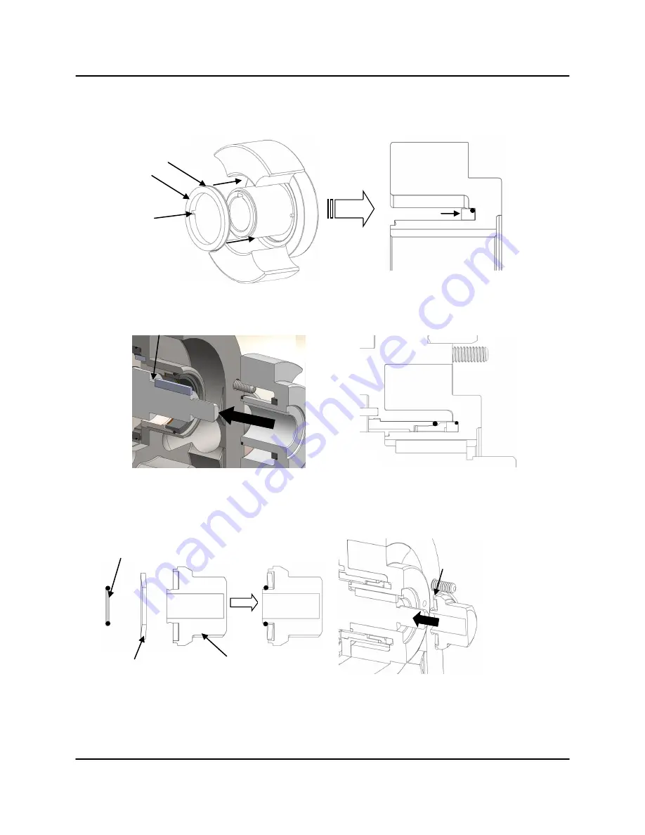
Slide the rotating seal onto the rotor hub (Figure 7) making sure to align the slots on the 

seal to the drive pins in the rotor.  Press the seal down until it seats inside of the rotor.  


5)  

Slide the rotors on to the shafts until they seat against the shaft shoulder (Figure 8).   


6)   

Install the Bellville washers in the rotor nuts in the orientation shown and hold them in place 

using the small retaining o-rings (Figure 9).  Install a rotor nut o-ring before threading the nut 
onto the shaft.   


Rotating Seal  

Rotating Seal O-ring 

Align 

Figure 7: Inserting Rotating O-ring 

Figure 8: Rotor Assembly 

Rotor Nut 

Bellville Washer 

Retaining O-ring 

Figure 9: Rotor Nut Assembly 

Rotor Nut O-ring 

Shoulder 

Summary of Contents for ZP3 Series

Page 1: ...Ampco ZP3 Series Addendum Positive Displacement Pumps Installation and Maintenance Manual ...

Page 2: ... washer and retaining o ring Figure 2 Rotor Removal 3 Remove the rotors by orientating them perpendicular to each other and then pulling them out It is important to be cautious with the rotors so that they are not damaged in any way If rotors are difficult to remove use a nylon or wood lever to pry them out without damaging the body or the rotors Use Figure 3 to ensure that all parts are removed P...

Page 3: ...y installed Align the slots on the stationary seal with the pins inside the hub Press the stationary seal into the hub until is seats on the spring there should be noticeable spring resistance when pushing on the seal 3 Next install the rotating o ring onto the rotating seal by stretching it not rolling onto the rotating seal Figure 6 Wave Spring Align the slot and pin Figure 4 Inserting Spring Fi...

Page 4: ... to the shafts until they seat against the shaft shoulder Figure 8 6 Install the Bellville washers in the rotor nuts in the orientation shown and hold them in place using the small retaining o rings Figure 9 Install a rotor nut o ring before threading the nut onto the shaft Rotating Seal Rotating Seal O ring Align Figure 7 Inserting Rotating O ring Figure 8 Rotor Assembly Rotor Nut Bellville Washe...

Page 5: ...ned under the overlap of the opposing rotor Repeat with the second rotor in the same orientation 8 Install a new cover o ring and slide the cover over the studs making sure that the dowels in the body are aligned with the correct dowel holes in the cover Figure 11 Visually inspect to ensure that the cover o ring remained in place Turn the cover nuts clockwise by hand and fully tighten them using t...

Page 6: ...rdance to Table 1 Use shims and a depth micrometer to measure the clearances Figure 12 Critical Pump Clearances Table 1 Critical Pump Clearance Dimensions Standard Rotors A Backface Clearance B Rotor to Body Clearance C Front Face Clearance Note For non standard rotors contact Ampco A Backface Clearance B Rotor to Body Clearance C Front Face Clearance ZP3 Model Inch mm Inch mm Inch mm 6 15 18 002 ...

Page 7: ...of wear and stress cracks around the areas defined in Figure 22 C Replace if necessary Check the pump clearances detailed on page 28 to determine pump wear Pump wear can be compensated by increasing pump speed Figure 22 Annual Maintenance Checks C Check Check Gears B Check Bearings A Cleaning All wetted parts are designed and manufactured to be acceptable by 3A Sanitary Standards The body rotors a...

Page 8: ...dale WI 53209 Phone 800 737 8671 or 414 643 1852 Fax 414 643 4452 Email ampcocs ampcopumps com For additional information on the ZP3 series and other Ampco Pumps products please visit our website www ampcopumps com Revision Date November 2011 ...

Reviews: