
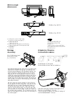

Abmessungen
Dimensions
Montage
Assembly
Allgemeine Hinweise
General Informations
Die mitgelieferte Montagefolie (Dicke 0,15 mm) wird zwischen
Abtastkopf und Messflansch eingelegt. Der Abtastkopf wird
leicht und gleichmäßig gegen den Messflansch gedrückt und
mit den beiliegenden Schrauben befestigt. (M4 mit 2,00Nm
Anzugsmoment) Mit der Montagefolie überprüfen, dass der
Luftspalt über die gesamte Abtastfläche konstant ist und über
der gesamten Messlänge innerhalb des zulässigen Toleranz
-
bereiches liegt. Die Punktmarkierung auf dem Messkopf muss
auf der gleichen Seite wie die Punktmarkierung auf dem Maß
-
band ausgerichtet sein!
Place the supplied spacer film (thickness 0.15mm) between
the scanning head and measuring flange. Press the scanning
head slightly and evenly against the measuring flange and
fix it with supplied screws. (M4 with 2,00Nm torque) Check
with the spacer film that the airgap is uniform over the whole
scanning surface and that the airgap is within the tolerance on
the complete measuring length. The „dot“-marking on the read
head, must be aligned on the same side as the dot marking on
the measuring tape!
Mindestabstand von Störquellen
Minumum distance from sources of interference
Elektrischen Widerstand zwischen Steckergehäuse und
Maschine prüfen.
Sollwert:
1 Ohm max.
Check the resistance between the connector housing and
machine.
Desired value:
1 Ohm max.
3 ±0,5
10
H2
4,5
49
61
73
3,5
4,5
19
7,45
0,8
22,5
H4
H1
29
3,5
16
H3
1 ±0,5
H3
H2
Mit Maßband Type LMB-1010
Mit Maßband Type LMT-4010
Tolerance priciple in accordance with ISO 8015
General tolerances in accordance with ISO 2768-fH
All dimensions in mm
Tolerierungsgrundsatz nach ISO 8015
Allgemeintoleranz nach ISO 2768-fH
Alle Maße in mm
Tolerierungsgrundsatz nach ISO 8015
Allgemeintoleranz nach ISO 2768-fH
Alle Maße in mm
Tolerance principle in accordance with ISO 8015
General tolerances in accordance with ISO 2768-fH
All dimensions in mm
H1 = Luftspalt 0,15 ± 0,10mm, mit Folie einstellbar
= Air gap 0,15 ± 0,10mm, set with spacer foil
H2 = Referenzspur-Markierung
= Reference track marking
H3 = Verfahrrichtung des Abtastkopfes für positive Zählrichtung
= Direction of scanning head movement for positive counting
H4 = Montagefläche
= Ground plane
M4 mit 2,00Nm Anzugsmoment
M4 with 2,00Nm Torque
M
d
= 2,00 ± 0,05Nm