background image

5.7.3 Screw con nec tions

With vi brat ing de vices, it is im por tant to check in ter mit tently the
screw con nec tions for tight ness. Pay at ten tion to the tight en ing
torque.

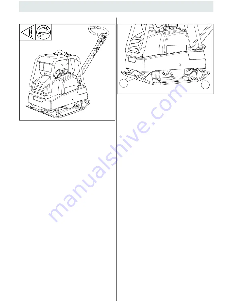
5.7.4 Check ing the rub ber buff ers

Check the rub ber buff ers (1) for tears and out breaks, as well as
for se cure fit. If they are dam aged, re place them im me di ately.

5. Main te nance

62

B3299092

1

1

B3299091

Summary of Contents for 10985720

Page 1: ...Translation of the original Operating instructions EN Book ID 2 00002021 APR 2220 Serial Nr 10985720 APR 2620 Serial Nr 11003014 APR 3020 Serial Nr 10985720 APR 3520 Serial Nr 11003032...

Page 2: ......

Page 3: ...nt in surance and prevention HVBG as well as the applicable ac cident prevention regulations Also observe the corresponding rules and regulations valid in your country Ammann Verdichtung GmbH is not l...

Page 4: ...ce instructions The following signs and designations are used in the manual to des ignate instructions of particular importance Transporting the machine Only load and transport the machine as specifie...

Page 5: ...erefore only use original spare parts Hydraulic lines must previously be rendered pressureless before working on them Hydraulic oil discharging under pres sure can cause serious injuries Work on hydra...

Page 6: ...eights Basic unit B1 121 kg 130 kg 213 kg 257 kg 100 kg 199 kg 242 kg Basic unit B2 128 kg 135 kg 217 kg 271 kg 205 kg 257 kg Transportation kit 8 kg 9 kg 10 kg 8 kg 10 kg Electrical starter 13 kg 15...

Page 7: ...irective in the version 2006 42 EC was determined taking into account the following standards and directives In operational use values can deviate depending on the prevailing conditions 9 1 Noise data...

Page 8: ...n only when set to the maximum forward travel setting a In any other position the control lever moves in the direction of maximum forward travel when released If the control lever is operated too quic...

Page 9: ...screw 2 the tow bar 1 can be set to any positions so as obtain the best working height on the tow bar grip 3 4 2 Locking the tow bar In case of loading and transport the tow bar 1 has to be locked in...

Page 10: ...til you feel resistance then pull briskly in the direction of the arrow as shown below Return the starter grip gently Important B3299087 MIN 1 B4899005 cdr OPEN CLOSE CLOSE 3 B4899004 cdr ON OFF ON 2...

Page 11: ...he OPEN posi tion as the engine warms up 3 5 3 Stopping the engine Set the engine speed lever 1 to the MIN position Turn the engine switch 4 to the OFF position Turn the fuel valve lever 2 to the OFF...

Page 12: ...of rope for the starting procedure II Take hold of the handle 2 with both hands Pull the starting rope with increasing speed until the motor starts up B3299089 1 MAX B1799202 cdr SCS 2 I II B1799203 c...

Page 13: ...e Set the engine speed lever 1 to idle MIN Allow the engine to run for 1 2 minutes APR 2220 2620 3020 Press motor stop button 4 until the motor stops running Release the stop button stop button must r...

Page 14: ...ts Indicator lamp 3 lights to show that the engine is operating Set the engine speed lever 1 to idle MIN Allow the engine to run for 1 2 minutes in order to warm up Attention The ignition key must spr...

Page 15: ...ts up Turn ignition key to 0 and remove APR 3520 Set the engine speed lever 1 to STOP Charging indicator 4 and oil pressure indicator 5 lights up Turn ignition key to 0 and remove 3 Operation 0 I II 2...

Page 16: ...Operation II I 0 1 2 MIN MAX B3299050 cdr Attention Operate the machine only at full throttle and turn the machine always in idle position during short rest periods Otherwise Danger of clutch damages...

Page 17: ...the contact points frame lifting rings be fore use for damage and wear Immediately re place damaged parts Secure the machine against rolling or slipping off and against tipping over Ensure that no per...

Page 18: ...the machine on to the front edge the undercarriage will swing under the board B3299081 3 2 B3299080 1 Danger During longer work breaks e g at the end of the work day do not place the machine on the tr...

Page 19: ...e backwards until the ma chine is horizontally seated on the undercarriage The device is ready to be moved After transport hook the undercarriage back into position by proceeding in reverse order 1 Sp...

Page 20: ...aning the machine with a high pressure water jet do not spray the electrical components directly After washing the components blow dry them with com pressed air in order to prevent surface leakage cur...

Page 21: ...esidual mineral oil content should be reduced acc to VDMA specification 24 569 MOBIL a Mobilfluid 424 b Mobilfluid 426 Mobil DTE 24 Univis N 46 ATF 220 FUCHS Titan Unic MC Titan ATF 3000 Agrifarm UTTO...

Page 22: ...o the oil filler neck as shown but do not screw it in then remove it to check the oil level If the oil level is near or below the lower limitmark on the dip stick fill with the recommended oil to the...

Page 23: ...he foam Wipe dirt from the inside of the air cleaner case and cover us ing a moist rag Be careful to prevent dirt fromentering the air duct that leads to the carburetor Place the foam air filter eleme...

Page 24: ...p the engine Clean the area around the dipstick 5 Withdraw the dipstick 5 and wipe with a clean fibre free cloth To check the oil screw the dipstick back in and then remove it again Check the dipstick...

Page 25: ...max 5 bar from the inside outwards until no more dust comes out Care refit filter element 2 Fit cover 1 B5399017 cdr 2 B5399016 cdr 1 B5399018 cdr 2 B5399020 cdr 3 B5399019 cdr max 5 bar Danger Risk o...

Page 26: ...lubrication is used 5 Maintenance Attention For cleaning do not use any flammable or aggres sive materials When cleaning the machine with a pressure washer do not spray the electrical components di re...

Page 27: ...mittently the screw connections for tightness Pay attention to the tightening torque 5 7 4 Checking the rubber buffers Check the rubber buffers 1 for tears and outbreaks as well as for secure fit If t...

Page 28: ...uxiliary tools 6 mm into bores 2 and 3 Tension vee belt by turning clutch halves 2 and 3 in oppo site directions Tension clutch halves 2 and 3 X 10 mm Crank the drive manually and re check tension and...

Page 29: ...n and top up with oil if necessary 5 Maintenance Important Check change exciter oil when its warm APR 3520 The venting screw 3 must always first be unscrewed when checking the oil level or changing th...

Page 30: ...ew 1 5 7 9 Hydraulic hose lines 1 Ammann Article No 2 Manufacturer Month and year of manufacture 3 Max operating pressure The function of hydraulic hose lines must be tested at regular in tervals mini...

Page 31: ...n Move lever to CLOSE position Gap or replace spark plug Dry and reinstall spark plug HONDA HONDA Unless the engine is warm HONDA HONDA Start engine with throttle lever in MAX position Engine stops by...

Page 32: ......

Reviews:

Related manuals for 10985720