


©Copyright AMKUS Rescue Systems, Inc. 2016-2019
LAC-003 May 20, 2019 Rev05
6
5.0 SET-UP PROCEDURE
AMKUS manufactures equipment of superior craftsmanship and quality. Amkus backs new products with a standard warranty
published on the AMKUS website, amkus.com
NOTICE
Only use AMKUS tools with AMKUS equipment. Mixing AMKUS tools with another manufacturer’s
equipment may cause operational problems, equipment failure, or denial of warranty claims.
NOTICE
Only use AMKUS mineral-base hydraulic fluid in AMKUS equipment. Using another manufacturer’s
hydraulic fluid in AMKUS equipment may cause operational problems, equipment failure, or
denial of warranty claims.
Normally, AMKUS dealers prepare and service equipment prior to delivery. If, however, you decide to place the equipment into
service yourself, please review the following instructions carefully.
1. Remove equipment from the packing cartons and carefully inspect for damage. Damage occurring during shipment should be
reported immediately to the carrier.
2. Gather and review all safety and use documentation prior to operating any rescue tool.
3. Connect the tool connection hoses to the hose lines from the AMKUS hydraulic power unit.
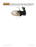
a. Standard Couplings: Please note that the male and female couplings on the hose lines leading from the power unit should be
connected to the corresponding male and female couplings on the tool connection hoses. To connect the couplings, twist the
sleeve on the female coupling so that the notch in the sleeve lines up with the pin. Push the sleeve back so the pin fi ts into the
notch. While holding the sleeve back, push the male coupling into the female coupling. Release the sleeve; it will spring forward
into place. Twist the sleeve 1/4 turn so that the pin no longer lines up with the notch. Pull on the couplings to check that they
are securely connected.
b1. Mono Couplings: Please note that the female coupling on the hose lines leading from the power unit should be connected
to the corresponding male coupling on the tool connection hoses. To connect the couplings, place the male coupling into
the female coupling. Rotate clockwise until you feel the coupling latch. Pull on the couplings to check that they are securely
connected.
b2. In most cases, the Mono Couplings can be connected and disconnected while the hose line is under fl ow. It is usually not
necessary to place the directional control of the power unit in the neutral position before connecting and disconnecting.
However, certain circumstances such as back pressure in the return line and/or cold temperatures, may make connecting and
disconnecting under fl ow extremely diffi cult or impossible. If you are unable to connect and disconnect while the line is under
fl ow, place the directional control valve of the power unit in the neutral position and then disconnect or connect.


